Recognition display PWM dimming test is a five-minute commissioning step that many athletic directors and facilities teams skip—until they notice horizontal stripes rolling through a photo taken at a recognition event, a staff member reports eye strain during a long lobby shift, or a video recording of an induction ceremony shows the hall-of-fame wall flickering on screen. PWM stands for Pulse Width Modulation, the brightness-control method most commercial display panels use to reduce backlight intensity without altering driver voltage. At low brightness settings—common in naturally lit lobbies during the day, in evening standby modes, or in photo-controlled display installations—PWM cycling frequency directly determines whether the recognition display flickers visibly, flickers on camera, or holds a stable, steady image.
This guide gives school administrators, athletic directors, archives staff, facilities teams, and recognition-program owners a documented test protocol, an interpretation table, a printable checklist, and a practical response framework for any recognition touchscreen or digital wall-of-fame display running below full brightness.
School recognition displays serve high-visibility spaces: trophy case alcoves, main lobby entrances, athletic hall-of-fame corridors, and event staging areas where photographs are taken regularly. A display that flickers at low brightness in those contexts undermines the recognition experience and can create accessibility concerns for photosensitive visitors. Running a systematic dimming test at commissioning—and again after any firmware or brightness-setting change—protects both the display investment and the experience it creates.

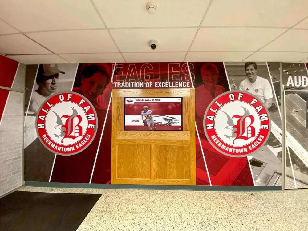
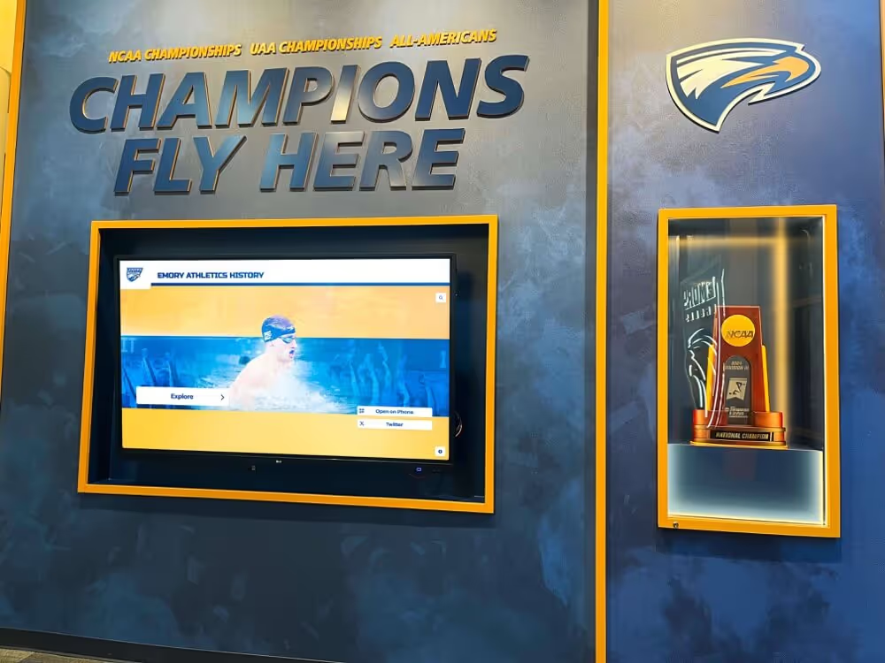
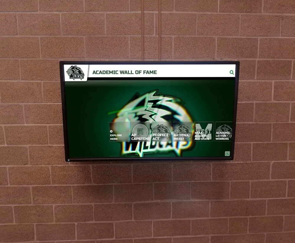
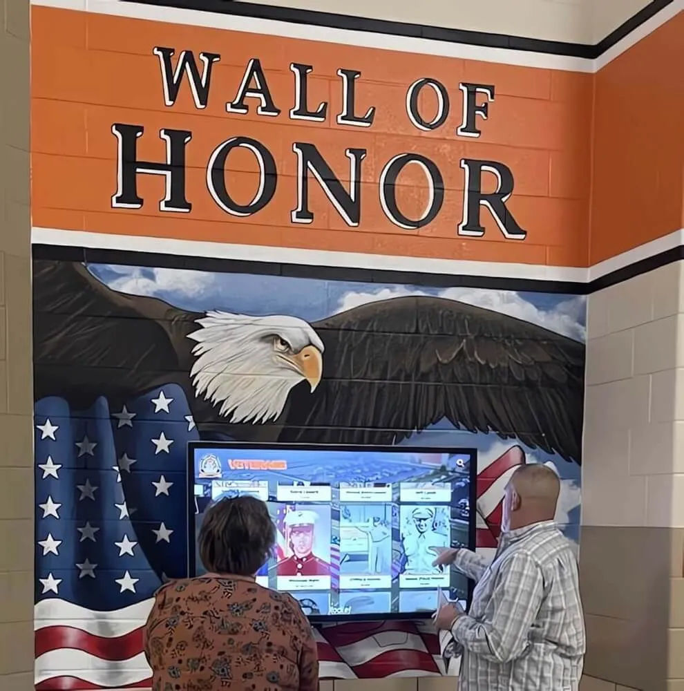
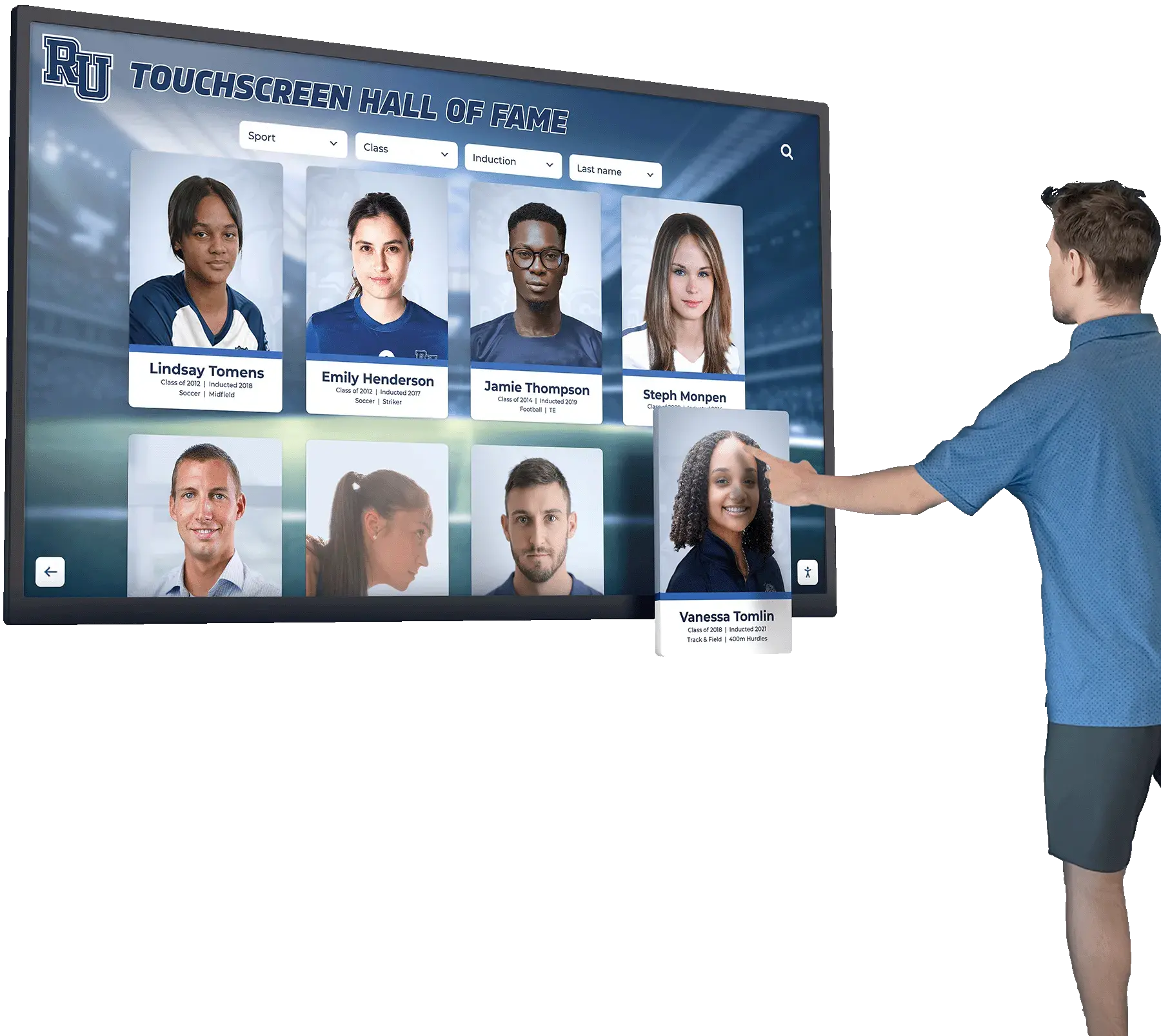
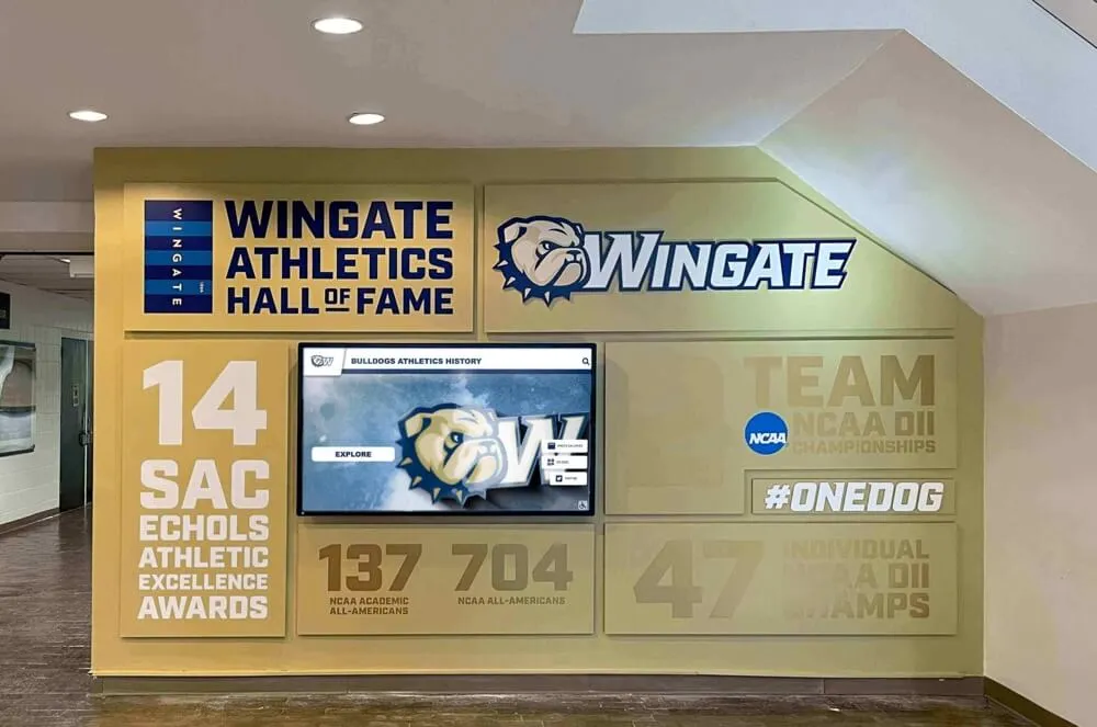
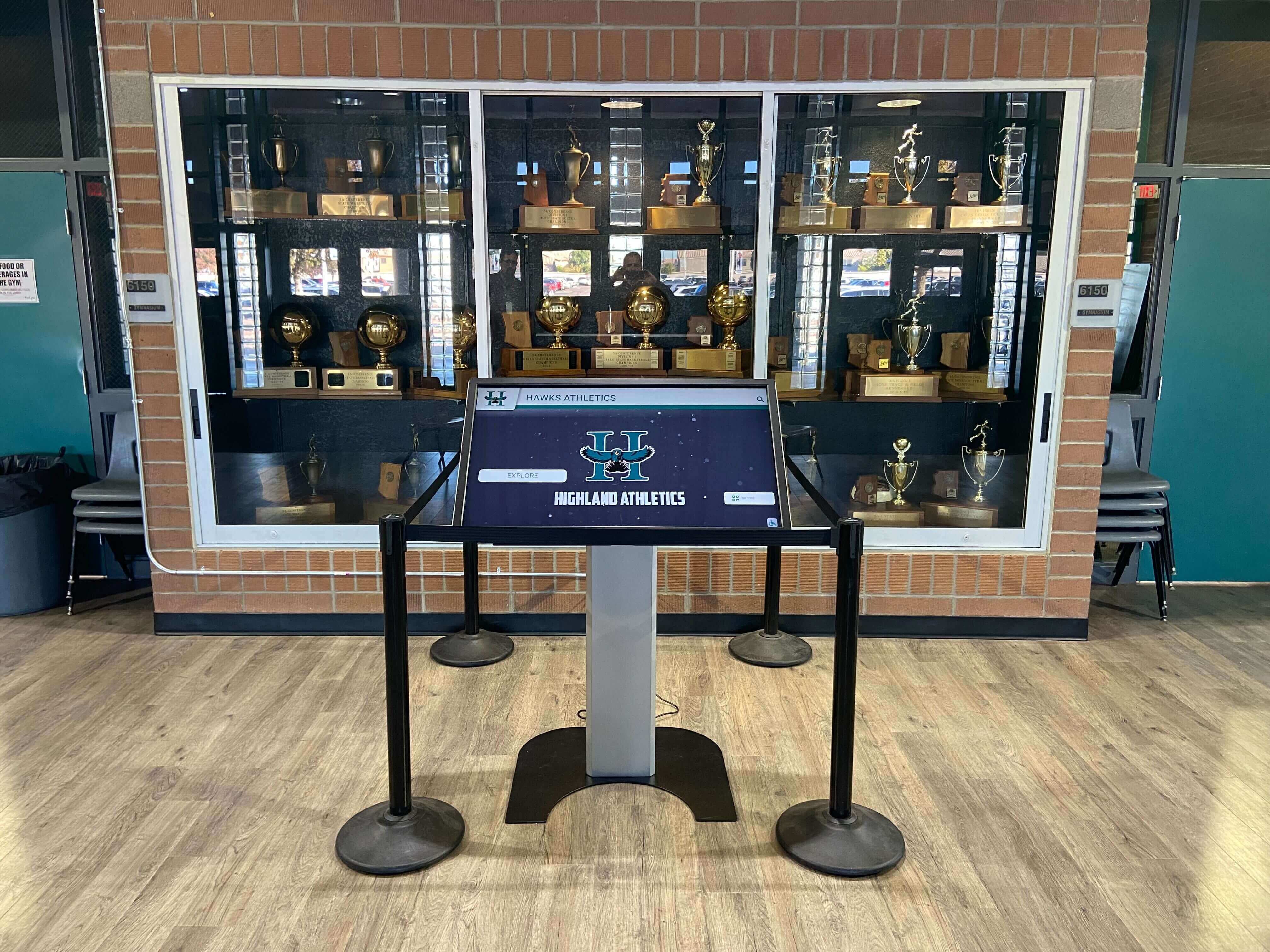
Recognition touchscreens installed in trophy case areas often run below full brightness—making PWM behavior a key commissioning variable before public deployment
What PWM Dimming Is and Why It Matters for Recognition Displays
Most LCD and LED-backlit panels cannot simply reduce the voltage driving the backlight to create a dimmer image—reducing voltage causes color shift, uneven illumination, and instability in all but the most expensive panel designs. Instead, panel manufacturers use PWM: the backlight is switched on and off at a fixed frequency, and the duty cycle (the percentage of each cycle during which the light is on) determines perceived brightness. At 100% brightness, the backlight is effectively always on. At 50% brightness, the light cycles on and off at equal intervals. At 30% brightness, the backlight is off for 70% of each cycle.
The Frequency Problem at Low Brightness Settings
PWM frequency is the key variable. High-frequency PWM cycling—typically 1,000 Hz and above—produces flicker that no human eye perceives because the on/off transitions happen far faster than the visual system can resolve. Low-frequency PWM cycling—commonly 60 Hz, 120 Hz, or 240 Hz on commercial and budget display panels—produces flicker that a meaningful percentage of observers notice directly, and that virtually any camera captures as rolling horizontal bands at certain shutter speeds.
For recognition displays, the frequency problem compounds because school environments deliberately lower brightness in several common scenarios:
- Daytime ambient auto-dimming: Light sensors reduce brightness in well-lit lobbies to prevent glare on the touchscreen surface
- Standby and idle modes: Displays reduce brightness when no active user interaction has occurred for a set period
- Evening or overnight modes: Scheduled brightness reduction for after-hours or weekend operation
- Manual reduction by staff: Facilities teams lowering brightness during events to reduce glare on video walls or improve photographic conditions nearby
Each of these scenarios increases the proportion of each PWM cycle during which the backlight is off—amplifying the flicker effect relative to a full-brightness display. The lower the brightness setting, the more pronounced the flicker becomes for any given PWM frequency.
DC Dimming as the Alternative
Some displays—particularly higher-end professional and commercial-grade panels—offer DC dimming (Direct Current dimming) as an alternative or supplement to PWM. DC dimming reduces backlight voltage directly rather than cycling it, eliminating the flicker source entirely. The trade-off is that very low brightness settings with DC dimming can introduce color shift: the display image looks slightly different in hue at 20% brightness compared to 100% brightness. For recognition displays showing athletic photographs, school colors, alumni portraits, and institutional graphics, color accuracy at low brightness is a meaningful operational consideration.
Knowing whether a prospective display uses PWM-only, DC-only, or hybrid dimming is a question worth posing to the display vendor during procurement—and verifying through the test protocol below after installation.
Why School Recognition Displays Carry Higher Flicker Risk
Recognition displays occupy a different operational environment than classroom monitors or administrative workstations, and several factors make flicker behavior more consequential in this context.
Extended idle periods at reduced brightness. Recognition kiosks may run in reduced-brightness idle mode for four to eight hours per day during low-traffic school periods. A display experiencing low-frequency PWM flicker runs that flicker continuously, affecting anyone passing through the lobby or hallway.
Photography and video at recognition events. Induction ceremonies, award presentations, athlete appreciation nights, and end-of-season banquets involve photography near or of the recognition display. PWM flicker invisible to the naked eye appears as horizontal banding at camera shutter speeds that do not align with the PWM cycle—an artifact that affects every photograph of a recognizable institutional moment.
Accessibility considerations for all visitors. Individuals with photosensitivity, vestibular disorders, or migraine sensitivity may report discomfort from flicker that other observers do not notice. Recognition spaces serve all members of the school community, including alumni, prospective families, and community guests who visit specifically to see the display.
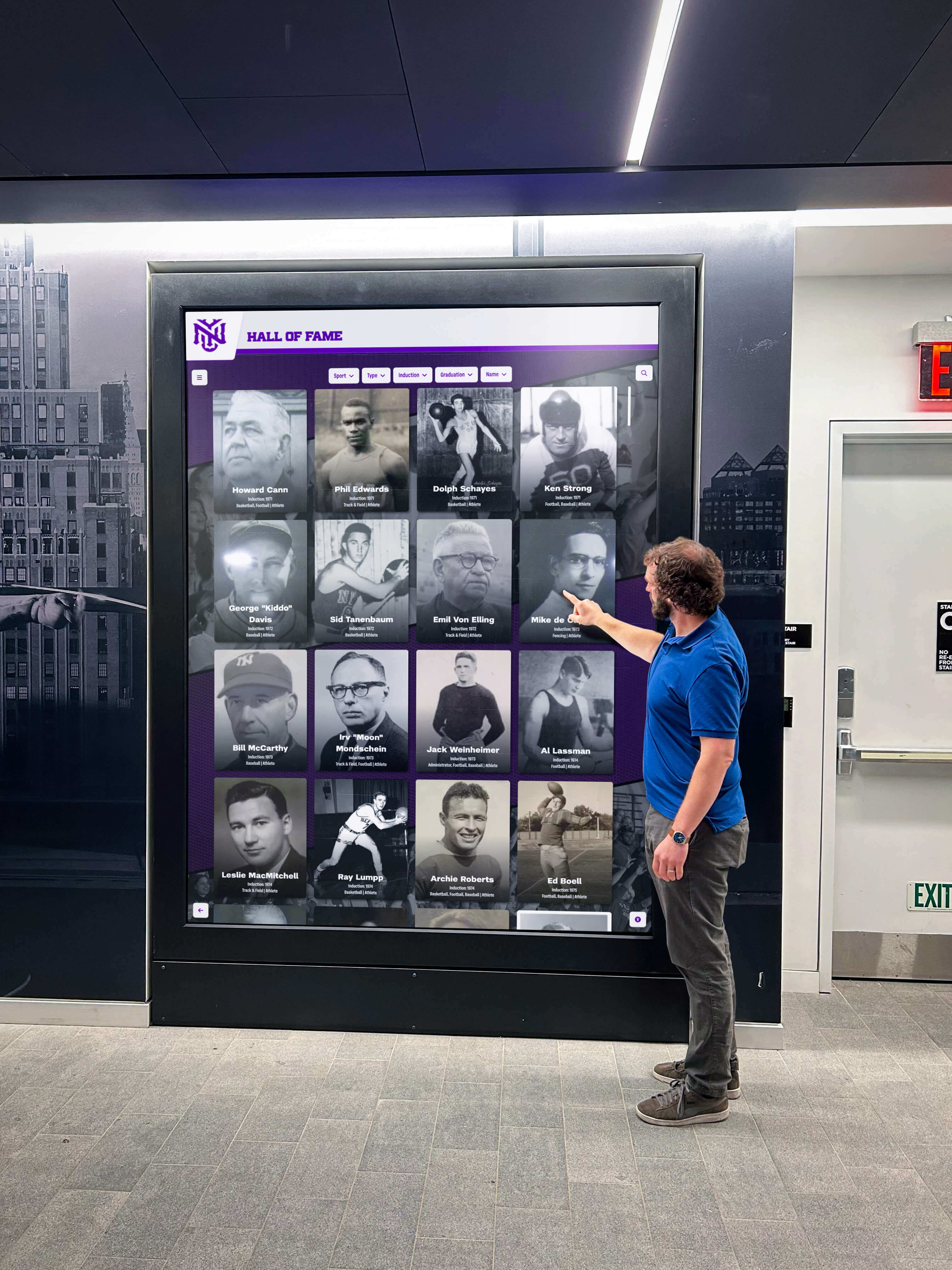
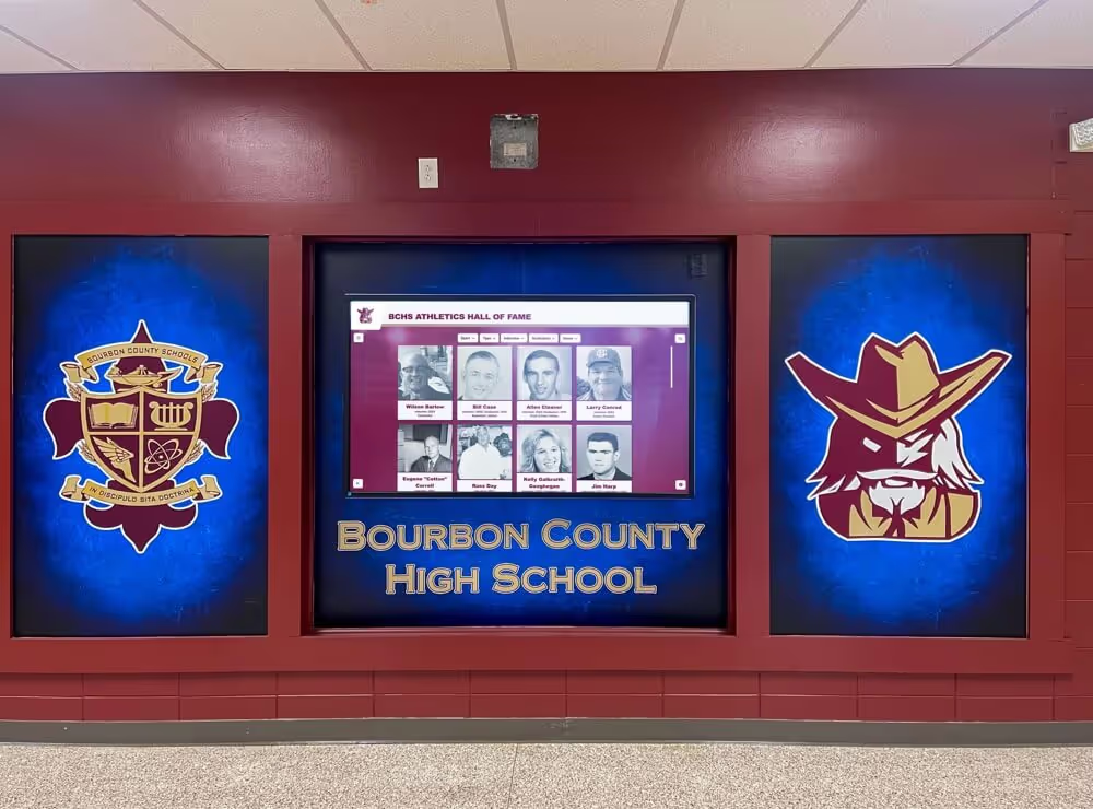
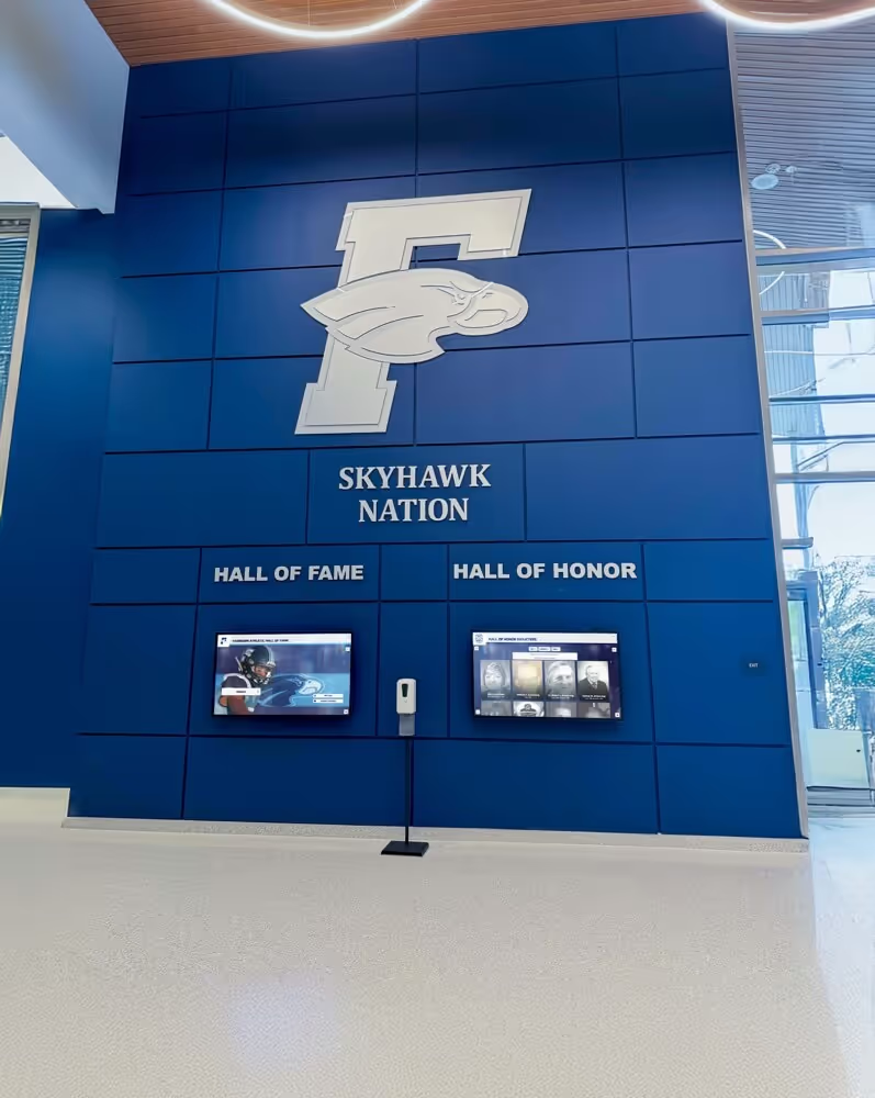
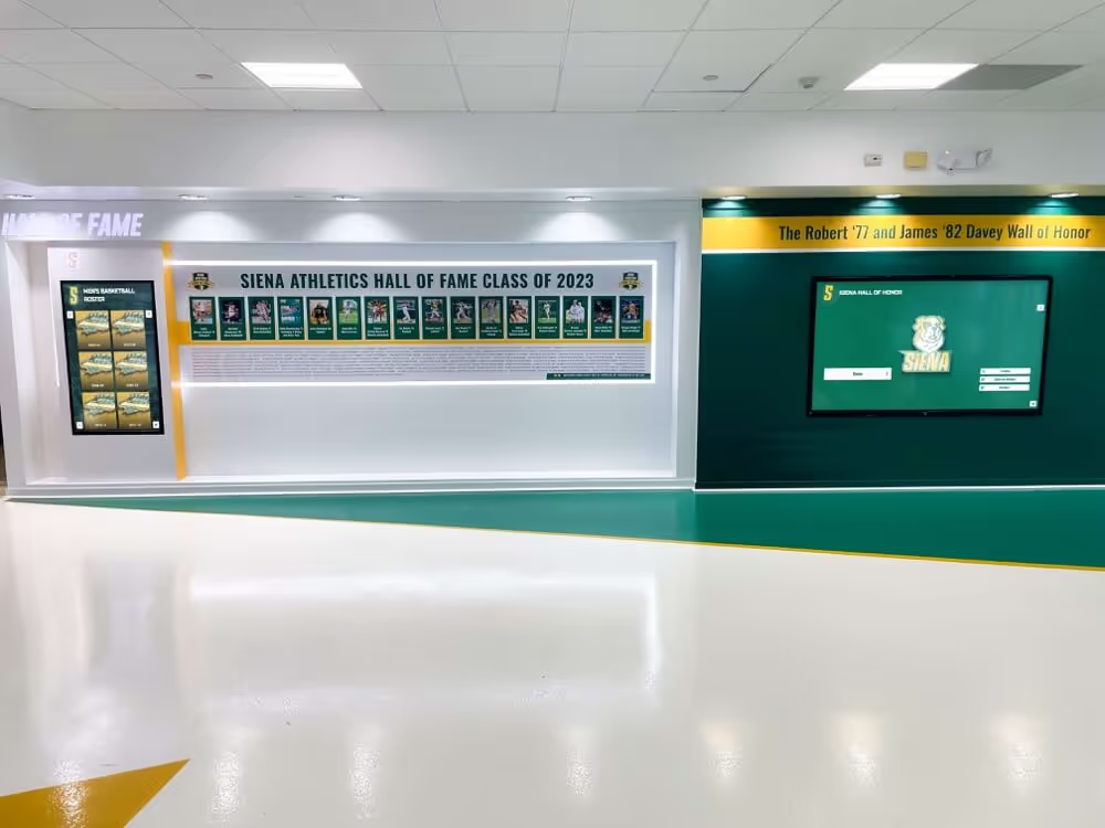
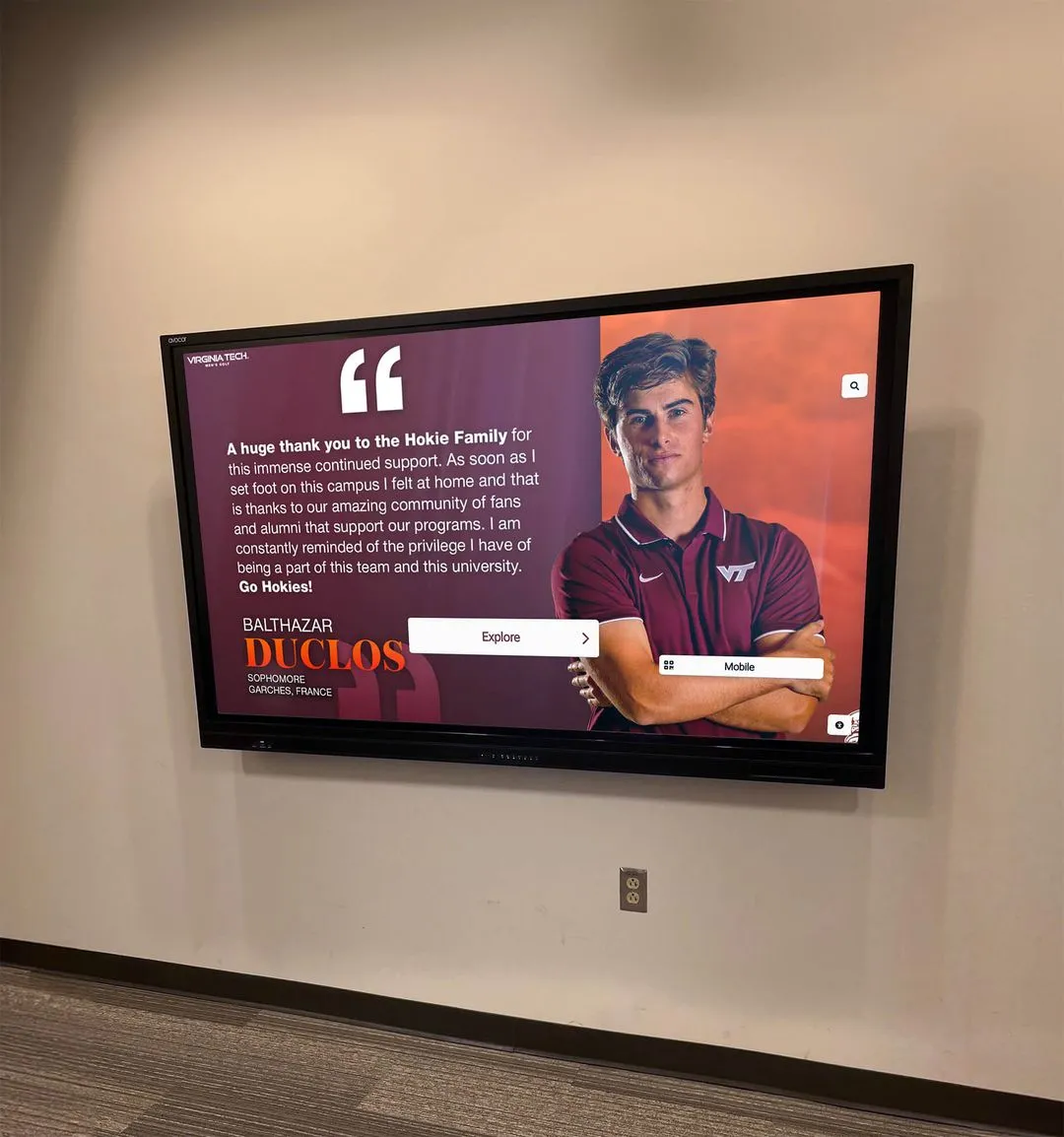
Lobby recognition displays serve varied audiences including alumni, prospective families, and community guests—making stable, comfortable viewing conditions essential
Schools evaluating display options should consider PWM behavior alongside brightness range, touch responsiveness, and panel longevity. A useful overview of panel technologies relevant to school deployment appears at best touchscreen options for schools, which compares display characteristics across common school use cases.
Who Should Run This Test
The recognition display PWM dimming test fits within the workflow of several school roles. The table below shows which situations call for the test and who typically owns each scenario.
| Role | When to Run the Test |
|---|---|
| Facilities Manager | At initial installation and after firmware or software updates |
| Athletic Director | Before major recognition events where photography or video recording is planned |
| Technology Coordinator | As part of annual display audit or A/V inventory review |
| Archives Staff | When the display is used to present scanned historic photographs or documents |
| Event Staff | Before video recording in spaces where the recognition display is in frame |
Any staff member comfortable using a smartphone and adjusting display settings can execute the camera-based portion of this test without specialized equipment. More structured measurement options—flicker meters, slow-motion video analysis—add precision but are not required for a preliminary pass/fail screening.
Equipment for the Recognition Display PWM Dimming Test
Required (no additional cost):
- Smartphone or digital camera with manual shutter speed control (available in pro photo mode on most current smartphones)
- Access to the display’s brightness control settings via OSD menu or CMS control panel
- Notepad or tablet for recording results
Optional (adds measurement precision):
- Slow-motion video mode (240 fps or higher): Available on most recent smartphones; reveals low-frequency flicker that standard video misses
- Flicker-meter or photodetector app: Some apps use the smartphone camera sensor to estimate flicker frequency; results are directional rather than calibrated but useful for initial screening
- Lux meter: Confirms actual brightness output at each tested setting, useful when comparing multiple displays during procurement evaluation
Note: Consumer flicker-meter apps vary widely in measurement accuracy. For technical documentation or procurement decisions, consult your display vendor for certified flicker measurements or engage an A/V professional for a calibrated session. This protocol is a commissioning screening tool, not a laboratory measurement.
Step-by-Step Recognition Display PWM Dimming Test Protocol
The following steps apply to any school recognition touchscreen, digital wall-of-fame display, or interactive kiosk where brightness is user-configurable. Complete the test when the display has been powered on for at least 30 minutes—the warmup period ensures stable backlight behavior before baseline measurements are taken.
Step 1: Document Baseline Conditions
Before adjusting any settings, record:
- Display model, serial number, and firmware version (available in the OSD menu under System or About)
- Current brightness setting as displayed in the OSD or CMS
- Ambient light level (describe as: dark / low / moderate / bright — or use a lux meter)
- Room location and time of day
- Whether auto-dimming, light sensors, or eco-mode features are active (disable these if possible to create consistent test conditions; re-enable after testing)
This baseline connects test results to a specific display configuration. If brightness settings are changed later, the record confirms which configuration was tested.
Step 2: Photograph the Display at Full Brightness
Set the display to 100% brightness. Using your smartphone in pro/manual mode:
- Set shutter speed to 1/100s
- Set ISO to 400
- Frame the display so it fills most of the camera view
- Take three photographs
What to look for: Horizontal bands (lighter and darker strips running across the image) indicate the camera is resolving a PWM cycle. A uniform, band-free image at 100% brightness suggests either no PWM or a frequency high enough that this shutter speed cannot resolve the cycle. Record whether banding is present, minimal, or absent.
Step 3: Test at 50% Brightness
Reduce display brightness to 50% through the OSD menu. Wait 60 seconds for the backlight to stabilize. Take photographs at three shutter speeds: 1/100s, 1/200s, and 1/500s.
Interpreting banding patterns at 50%:
- No banding at any shutter speed: PWM frequency is likely high enough to be unproblematic for typical camera use.
- Banding at 1/500s but absent at 1/100s: PWM frequency is in a range where banding is shutter-speed dependent—generally manageable in controlled photo conditions with photographer guidance.
- Banding visible consistently at multiple shutter speeds: PWM frequency is low enough to warrant further investigation and vendor contact.
Step 4: Test at 30% Brightness
Low brightness settings are where PWM-related flicker is most pronounced. Reduce the display to 30% brightness, then:
- Complete the photograph sequence at 1/100s, 1/200s, and 1/500s
- Record a 10-second slow-motion video at 240 fps (available in the camera apps of most current iOS and Android devices)
- Play back the slow-motion video and observe for visible pulsing or banding across the display panel
- Stand at the display’s typical viewing distance and observe the screen directly for 30 seconds—note whether any visual pulsing is perceptible and whether a brief gaze away then back creates a visible afterimage (an indicator of pronounced low-frequency flicker)
Step 5: Test at the Planned Operational Brightness
Most recognition displays run at a specific planned brightness during school hours, events, or standby mode—not necessarily at 50% or 30%. Identify the planned operational brightness from your display vendor’s recommendation or your facility team’s preferred setting, and repeat the photograph sequence at that exact value. This step directly tests the conditions the display will actually experience during daily operation.
Step 6: Evaluate Color Consistency for DC Dimming Displays
If the display vendor indicated DC dimming support, photograph a solid white region of the display at 100% brightness and again at 30% brightness. Compare the images side-by-side on the phone screen or laptop. A noticeable yellow, blue, or warm shift at low brightness indicates DC dimming is affecting color reproduction—relevant if your display presents athlete photographs, school color graphics, or scanned historical materials where accurate color matters.
Step 7: Document Results and Assign a Classification
Save all photographs and video in a labeled folder linked to the display’s maintenance record. Assign one of the four result classifications from the table in the next section. Document any follow-up actions and schedule the next re-test date.
Recognition Display PWM Dimming Test Checklist
Complete one checklist per display and retain in the display’s maintenance file. Repeat at commissioning, after firmware updates, and before major recognition events.
Pre-Test Setup
- Display powered on for at least 30 minutes before testing
- Display model, serial number, and firmware version recorded
- Auto-dimming, light sensors, and eco-mode features disabled for test duration (re-enable after)
- Baseline brightness setting documented
- Ambient light conditions described
- Camera set to manual/pro mode with adjustable shutter speed
Full Brightness Test (100%)
- Three photographs taken at 1/100s shutter speed
- Images reviewed for horizontal banding
- Banding observed: None / Minimal / Present
- Notes: ___________________________
50% Brightness Test
- Photograph sequence completed at 1/100s
- Photograph sequence completed at 1/200s
- Photograph sequence completed at 1/500s
- Banding pattern documented across shutter speeds
- Banding severity: None / Shutter-speed dependent / Consistent across speeds
30% Brightness Test
- Photograph sequence completed at 1/100s, 1/200s, and 1/500s
- 10-second slow-motion video recorded at 240 fps
- Slow-motion video reviewed for pulsing or banding: Yes / No
- Direct visual observation completed (30 seconds at viewing distance)
- Visible flicker perceptible to observer: Yes / No
Planned Operational Brightness Test
- Planned operational brightness setting: _______%
- Photograph sequence completed at that setting
- Result consistent with or different from 50% / 30% test: _______
Color Consistency Check (DC Dimming Displays)
- White field photographed at 100% brightness
- White field photographed at 30% brightness
- Color shift observed: Yes / No / Marginal
- Shift direction if noted: _______
Final Documentation
- All photographs and video saved in labeled folder
- Result classification assigned (see table below)
- Follow-up action documented
- Next scheduled re-test date recorded
- Checklist filed in display maintenance record
Result Classification Table
Use the following reference to assign a result classification after completing the test. The classification drives the specific follow-up action for each display.
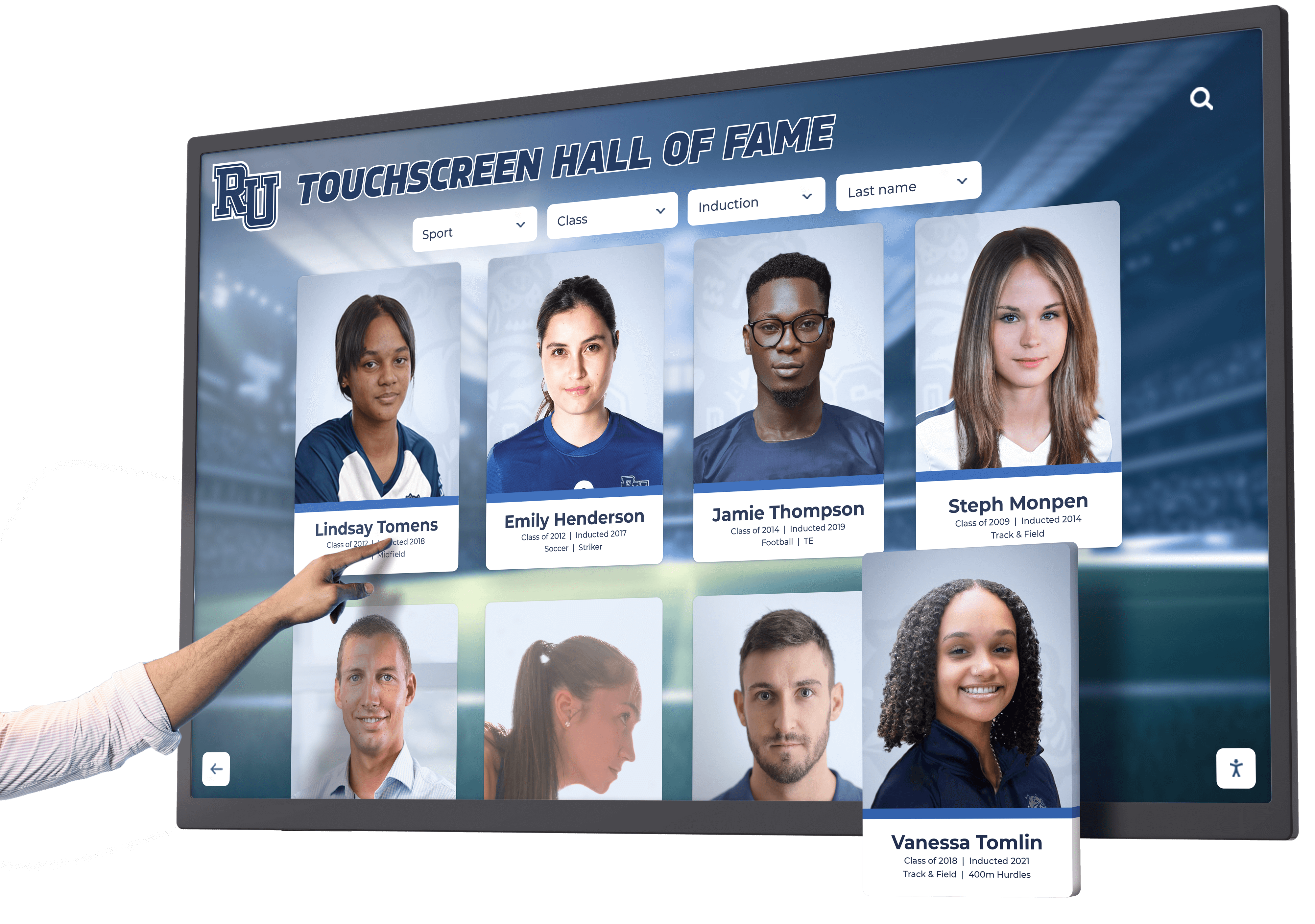
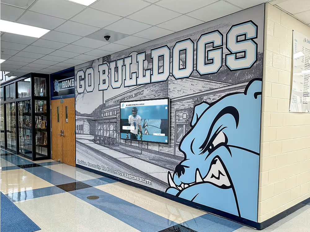
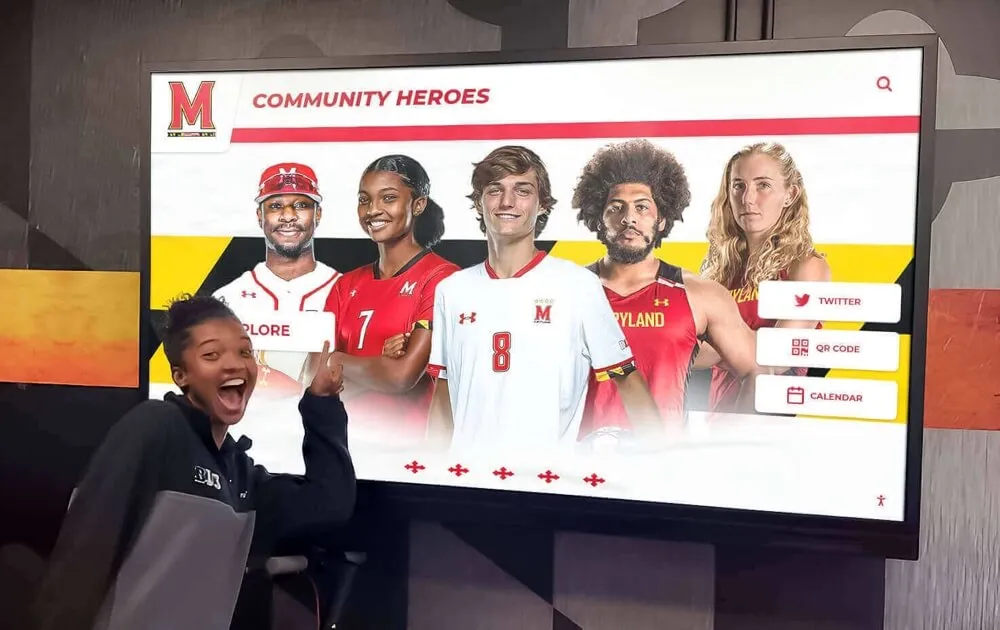
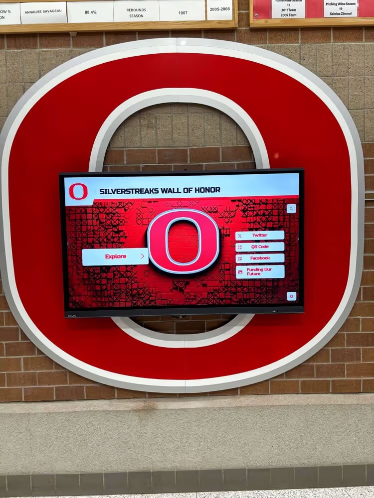
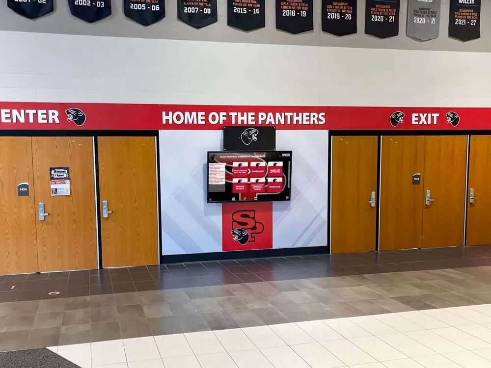
Recognition displays used for interactive browsing and event photography require stable image output at all operating brightness levels
| Classification | Observed Conditions | Recommended Action |
|---|---|---|
| Pass — No Concern | No banding at any test shutter speed; no visible flicker at direct observation; slow-motion video shows no pulsing | Deploy at planned brightness; re-test after firmware updates; no display-side restrictions on event photography |
| Pass — Camera-Managed | Banding visible at 1/500s or faster but absent at 1/100s; no perceptible flicker to observer | Deploy at planned brightness; brief event photographers to use shutter speeds at or below 1/100s when the display is in frame |
| Monitor — Low-Frequency PWM | Banding visible at 1/200s or consistently across multiple shutter speeds; or mild perceptible pulsing at 30% brightness | Contact vendor to confirm PWM frequency and firmware update availability; consider raising the operational brightness setting to reduce the duty-cycle effect; re-test after any change |
| Act — Significant Flicker | Consistent banding at 1/100s and faster; perceptible pulsing to the naked eye at normal viewing distance; slow-motion video shows clear, repeated pulsing | Do not deploy at current brightness setting; contact vendor with test documentation; request PWM specifications and hardware or firmware remediation; evaluate alternative display hardware if no vendor fix is available |
Frequently Asked Questions
What PWM frequency is acceptable for a recognition display in a school lobby?
Flicker research generally treats 1,000 Hz as a threshold above which most observers—including those with documented photosensitivity—report no adverse effects from backlight flicker. Frequencies between 250 Hz and 1,000 Hz are unlikely to cause widespread visible flicker but may appear in camera captures at certain shutter speeds. Frequencies below 250 Hz, and particularly those around 60–120 Hz, are most associated with observer discomfort and persistent camera banding. Ask your display vendor for the PWM frequency specification in writing; if they cannot provide it, treat the display as requiring the full test protocol before deployment.
Our display vendor says it uses “flicker-free” technology. Do we still need to run this test?
Yes. “Flicker-free” is a marketing claim without a universal technical standard. Some displays labeled flicker-free use DC dimming at higher brightness levels and switch to low-frequency PWM at very low settings. Others have genuinely eliminated PWM across the full brightness range. Running the test protocol at 30% brightness is the most reliable way to verify that the “flicker-free” claim applies at the brightness levels your display will actually use in operation.
We noticed banding in photos from our Hall of Fame induction ceremony last year. Could this be the cause?
Possibly. Banding in event photographs appearing as horizontal light-and-dark stripes across a display in the frame is a classic PWM-camera interaction artifact. The effect is shutter-speed dependent—asking the photographer to shift to 1/60s or 1/100s often eliminates the banding in subsequent shots. The lasting solution is confirming the display’s PWM frequency and either adjusting operating brightness or working with the vendor on a firmware update. For background on recognition event planning that addresses display setup, resources on induction ceremony logistics include display-environment considerations relevant to formal recognition events.
Should we run this test on every display in the building, or only recognition-specific displays?
This protocol focuses on recognition displays—touchscreen kiosks, digital walls of fame, and interactive honor boards—because they operate continuously in public-facing spaces, often at reduced brightness, with a higher expectation of photographic documentation than classroom monitors or presentation screens. If your school has other public-facing interactive displays (donor recognition walls, campus directories, visitor welcome screens) that run continuously at variable brightness, applying the same test is reasonable.
Is this test relevant to displays that only run at full brightness?
If a display never reduces below 100% brightness, PWM dimming behavior does not affect the experience. However, very few recognition displays actually maintain full brightness at all times. Even displays without explicit user-facing brightness controls may be dimmed by auto-light sensors, OSD eco-mode settings, or manufacturer firmware defaults. Review the OSD settings for any active power-saving or brightness-reduction features before concluding that full-brightness operation is guaranteed.
What about OLED panels used in recognition displays?
OLED panels use different brightness-control mechanisms than LCD/LED-backlit displays, but some OLED implementations use PWM at lower brightness levels—the same test protocol applies. OLED displays carry an additional consideration for recognition-display use: static content (athlete name plaques, record leaderboards, or logo graphics that remain visible for extended periods) creates burn-in risk on OLED panels that should be discussed with your vendor separately from the PWM dimming question.
Connecting the PWM Dimming Test to a Broader Commissioning Workflow
A PWM dimming test is one component of a complete display commissioning checklist. Facilities teams and technology coordinators who approach commissioning systematically will recognize it alongside other verification steps that confirm a recognition display performs correctly across all of its operational requirements before public deployment.
Related commissioning checks worth running alongside the PWM test include:
- Touch accuracy calibration: Confirming that touch registration aligns precisely with visible targets, especially at screen edges where calibration drift is most common
- Browser and kiosk lockdown verification: Confirming the display’s software operates in a locked-down kiosk mode that prevents navigation outside the recognition application. Guidance for this step is covered in detail at touchscreen kiosk browser lockdown procedures
- Focus trap and keyboard navigation test: Confirming that keyboard navigation remains contained within the recognition application and does not expose operating-system controls or other applications. The focus trap testing framework at digital hall of fame focus trap testing covers this step in detail with a repeatable verification method
- Accessibility language and screen reader audit: Confirming that the recognition interface meets accessibility standards for screen readers and assistive technology users. A parallel audit framework for web-based recognition displays is described at digital hall of fame accessibility auditing
- Color calibration check: Confirming that the display’s color profile accurately represents school colors, athlete portrait photography, and institutional graphics at full and reduced brightness
For teams building a comprehensive commissioning log, the approach used in athletic archive scanner calibration records provides a model for documenting multi-step technical verification results in a format that supports future reference and institutional continuity when staff changes occur.
What to Document After the Test
Complete documentation transforms a one-time commissioning test into an institutional record. Future staff members, display vendors, and facilities reviewers benefit from knowing exactly what was tested, at what settings, and with what result—without needing to reconstruct decisions from memory or repeat the test from scratch.
Minimum documentation for each display tested:
- Display identifier: model, serial number, and physical location
- Firmware version at time of test
- Result classification assigned
- Photographs and video files labeled with brightness setting and shutter speed
- Follow-up actions taken or scheduled
- Name of staff member who completed the test and date
- Date of next scheduled re-test
Store documentation in the display’s maintenance file, the facility’s A/V inventory record, or a shared drive accessible to both the technology coordinator and the athletic director. If the display is managed remotely through a content management platform, note the test results in the platform’s system record for that device so the information travels with the device rather than residing only with the individual who performed the test.
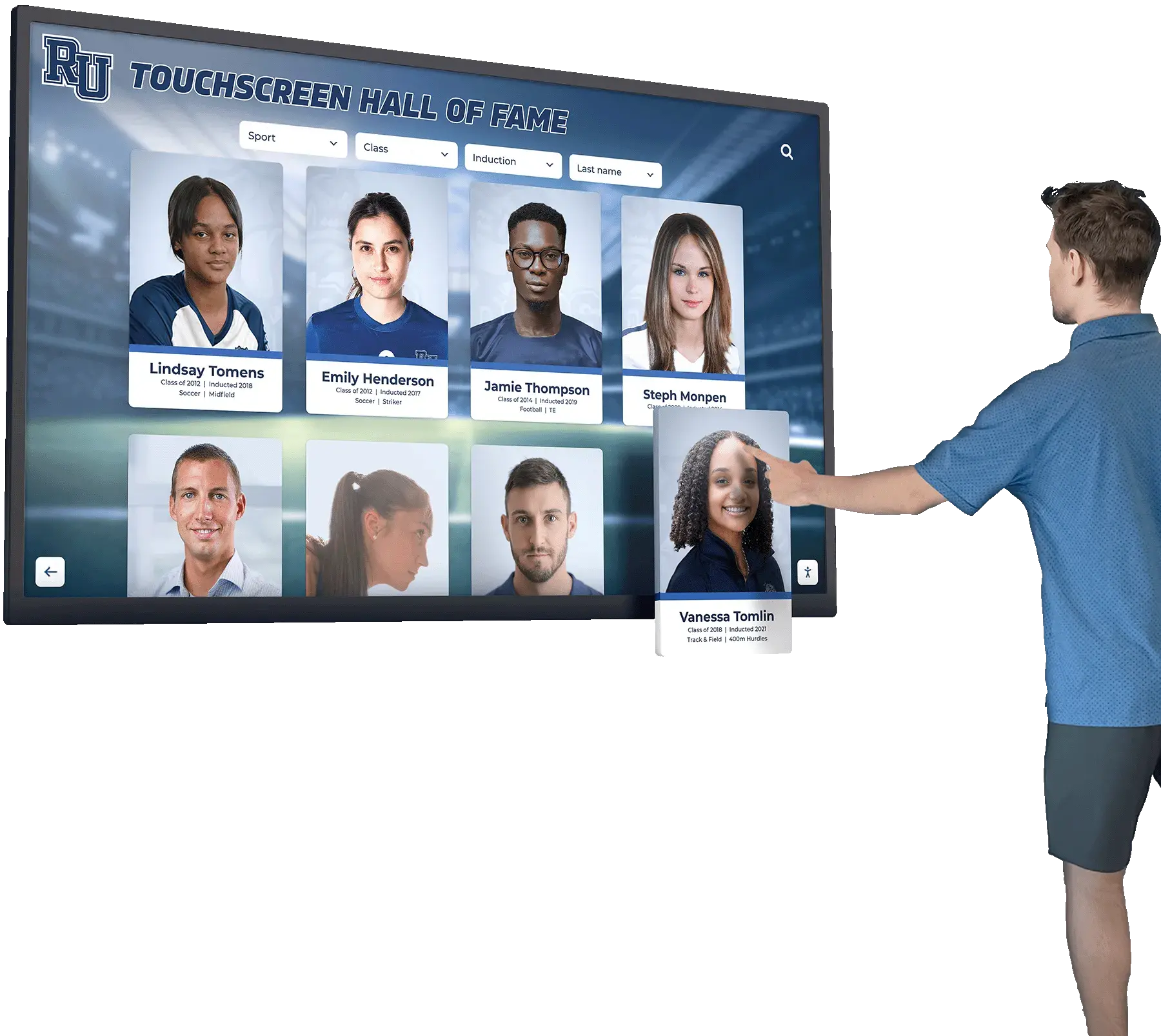
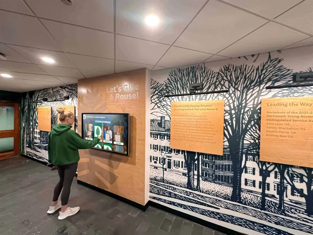
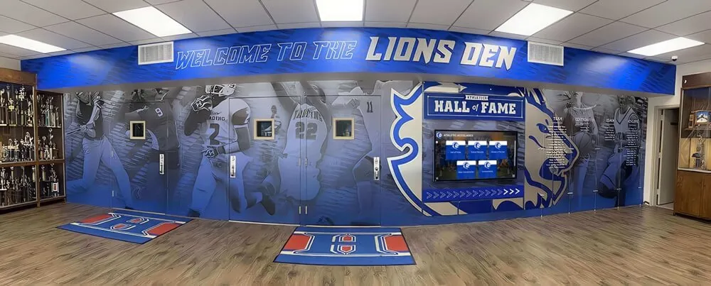
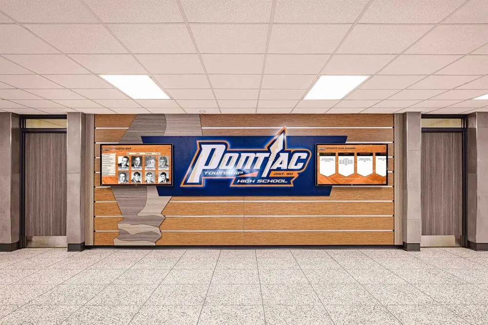
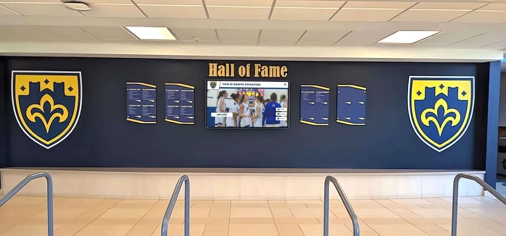
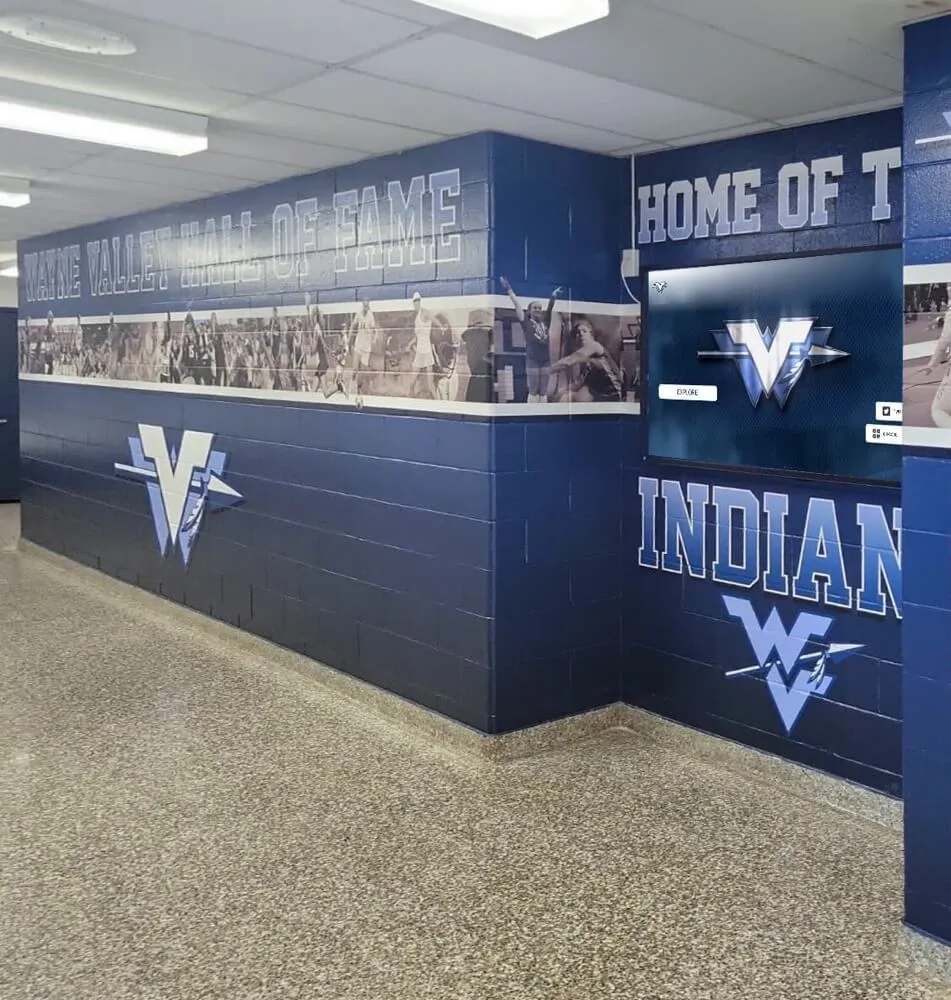
Well-commissioned recognition displays support confident interaction during daily lobby use, events, and formal recognition presentations
Recognition Display Platforms and PWM Dimming Considerations
Recognition display platforms vary in how they address brightness management—and in what technical information they make available to schools about PWM behavior in the underlying hardware.
Web-based platforms on school-supplied hardware: Some platforms run on commodity commercial displays where PWM behavior is determined entirely by the panel manufacturer. In this case, the platform provider may have limited visibility into PWM specifications, and the test protocol above is the most reliable verification tool available to your facilities team.
Integrated hardware-software packages: Some providers supply the display hardware, mounting hardware, and software as an integrated package. These vendors should be able to provide PWM specifications for the display hardware included in their package, and some have selected hardware specifically for favorable flicker performance across the brightness range used in school operation.
School-managed hardware procurement: Schools that select their own display hardware for recognition applications have full control over hardware choice and should build PWM frequency into their procurement criteria. Requiring a documented PWM frequency above 1,000 Hz—or DC dimming across the full operational brightness range—is a reasonable commissioning requirement to include in vendor specifications.
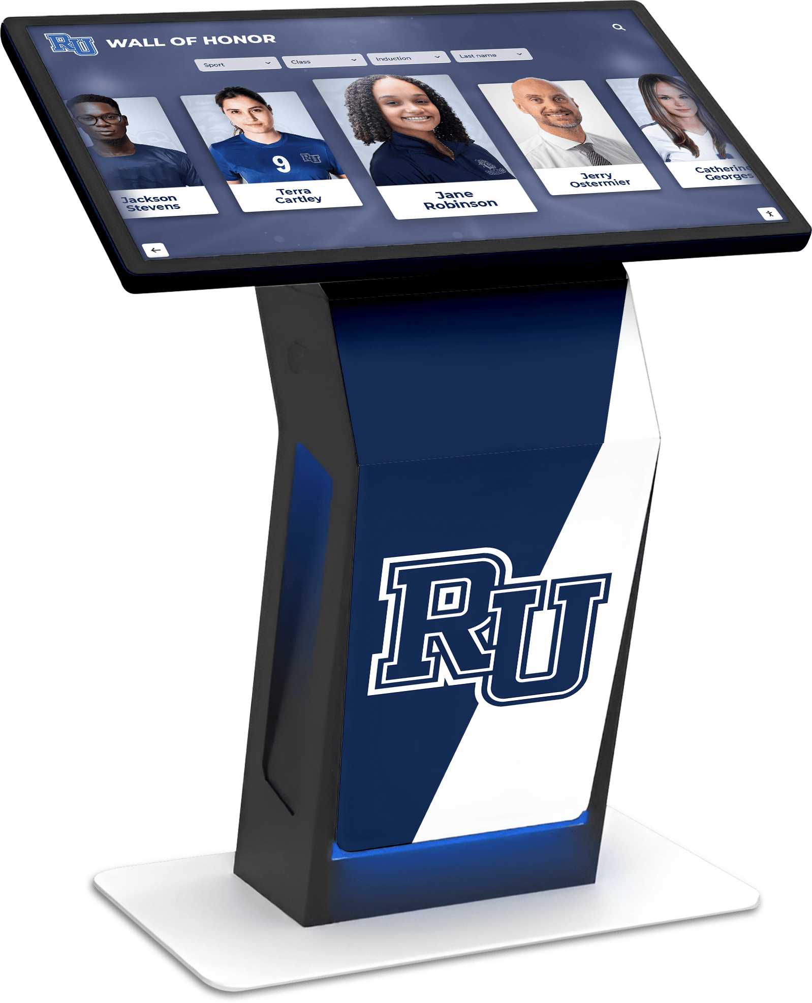
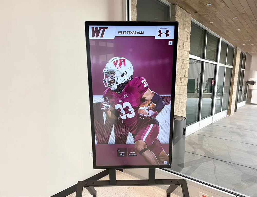
Web-based recognition platforms pair with a range of display hardware—making independent PWM commissioning tests a valuable step regardless of platform provider
When evaluating recognition display platforms, Rocket Alumni Solutions—a web-based platform designed specifically for school and institution recognition programs—uses a hardware-agnostic deployment approach, meaning PWM behavior in the underlying display is a hardware procurement decision your facilities team addresses using this test protocol alongside any vendor technical specifications.
Schools comparing recognition delivery formats and how they affect the physical display experience will find useful context at senior recognition ideas for school programs, which addresses the broader question of how schools design meaningful, lasting recognition experiences across physical and digital formats.
Practical Next Steps After the Test
Completing the recognition display PWM dimming test gives your team a clear picture of where each display stands. The appropriate follow-up depends directly on the result classification assigned.
Pass — No Concern: Document the result and set a re-test reminder linked to the next firmware update. Inform your events photographer that no shutter-speed restrictions apply when photographing near the display. Proceed with confidence in the display’s brightness behavior across its full operating range.
Pass — Camera-Managed: Prepare a one-paragraph briefing for any photographer shooting recognition events in the same room as the display. Note the recommended shutter speed ceiling (at or below 1/100s) and test this guidance before the event by taking a few test shots at the planned event lighting. A brief written note distributed before the event prevents a full ceremony’s worth of banded photographs.
Monitor — Low-Frequency PWM: Open a service inquiry with your display vendor referencing the test results, photographs, and slow-motion video. Ask for the PWM frequency specification and available firmware updates. Document the inquiry date and the vendor’s response. Re-test the display at the same brightness settings after any firmware update is applied.
Act — Significant Flicker: Pause public deployment at the current brightness setting until a vendor resolution is identified. Work with the vendor on hardware or firmware remediation options. If no resolution is available within a reasonable timeframe, factor PWM performance into your next display procurement decision and plan accordingly for recognition events in the interim.
For schools at an earlier stage—evaluating what type of recognition display to install before procurement—engaging a platform specialist who can address technical commissioning questions from the start reduces the likelihood of discovering a PWM problem after installation. Rocket Alumni Solutions works with schools throughout the recognition program lifecycle, from initial display selection and installation through content management, ongoing platform updates, and commissioning support.
Professional advice notice: This guide describes a practical commissioning screening protocol for school facilities teams managing recognition display installations. It does not constitute professional A/V engineering, electrical safety, or accessibility compliance advice. For calibrated flicker measurements, consult a qualified A/V professional. For displays with identified electrical concerns, engage a licensed electrician. ADA and applicable accessibility requirements take precedence over any general guidance presented here. District facilities guidelines and building codes govern installation decisions.