Intent: decide — A school lobby recognition kiosk and the guest Wi-Fi access point mounted three feet away may share the same physical switch, the same IP subnet, and the same VLAN number — yet under a correctly configured private VLAN architecture, those two devices cannot exchange a single IP packet directly. Private VLANs (PVLANs) enforce peer isolation at the switch hardware layer, preventing recognition displays from receiving unsolicited traffic from other kiosks, student laptops, visitor devices, or IoT equipment on the same segment, while still allowing each display to reach the upstream router, the content management system, and any authorized management hosts. Testing whether that isolation is actually working requires more than confirming the kiosk can load content — it requires verifying that the peer block is in place, that the promiscuous uplink is the only valid gateway, and that DHCP, DNS, NTP, and CMS connectivity are all preserved through the PVLAN architecture rather than broken by it.
This guide walks school IT coordinators, AV technicians, network administrators, and athletic directors responsible for recognition infrastructure through a structured school recognition display private VLAN isolation test. The test covers switch-level verification, active connectivity probing, and common misconfiguration patterns that produce silent failures — configurations that look correct in the switch CLI but silently break content delivery after the first lease renewal or the first reboot.
Private VLAN isolation is not a firewall policy. A firewall policy blocks traffic at a routing boundary after packets have already traveled across the Layer 2 segment. PVLAN isolation prevents packets from being forwarded across the segment at all — a fundamentally stronger guarantee for a recognition display that operates in a shared hallway or lobby environment alongside devices the district cannot fully control.

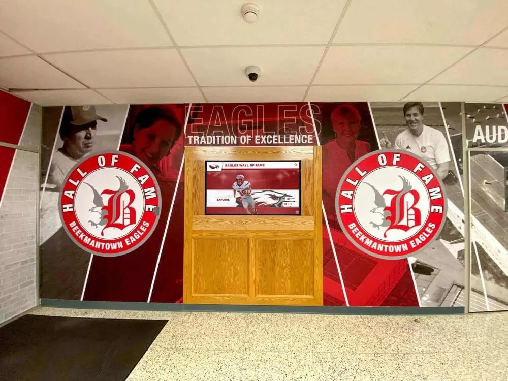
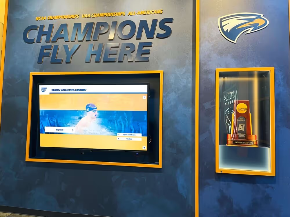
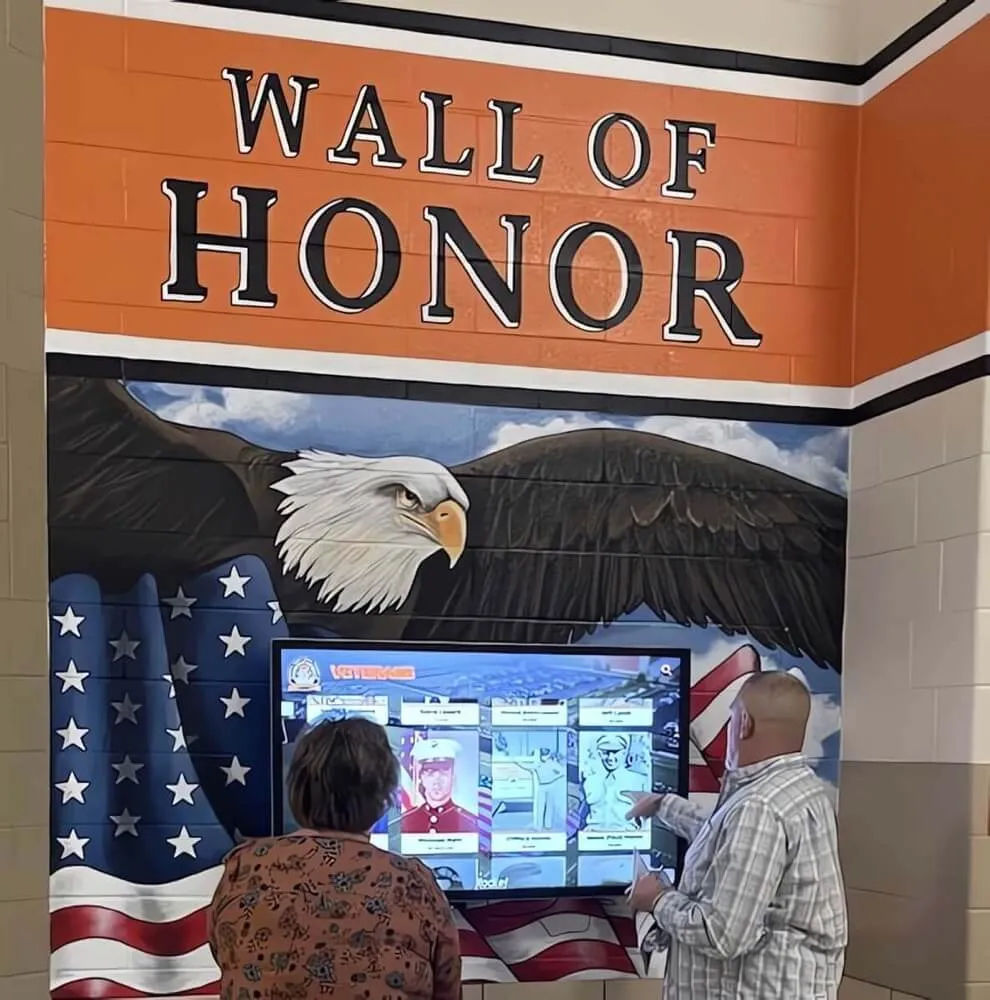
Recognition displays installed in shared school hallways and lobbies share physical switch infrastructure with student devices, visitor endpoints, and IoT equipment — private VLAN isolation ensures no lateral traffic path exists between them at the switch layer
What Private VLAN Isolation Means for Recognition Displays
Standard VLANs isolate broadcast domains between different groups of devices. All devices within a single VLAN can communicate directly with every other device in the same VLAN at Layer 2 — the switch forwards frames between them without routing. In a shared school network, a recognition kiosk on VLAN 40 can directly address any other device on VLAN 40, including student Chromebooks, BYOD phones, or guest access points that happen to share the same segment.
Private VLANs extend this model with secondary VLANs that enforce isolation within a primary VLAN. A primary VLAN is subdivided into three port types:
- Isolated secondary VLAN ports: Ports in an isolated secondary VLAN can communicate only with the promiscuous port. They cannot communicate with any other isolated port or any community port, even if all those ports share the same primary VLAN and the same IP subnet.
- Community secondary VLAN ports: Ports in a community secondary VLAN can communicate with other ports in the same community and with the promiscuous port. They cannot communicate with isolated ports or ports in a different community.
- Promiscuous port: Typically the uplink to the Layer 3 boundary — a router, a Layer 3 switch interface, or a firewall. A promiscuous port can communicate with all secondary VLAN ports regardless of type.
For a recognition display installed in a school lobby, the appropriate configuration is:
- Place the display’s switch port in an isolated secondary VLAN.
- Place the uplink to the router or Layer 3 interface in the promiscuous port.
- The display can reach the router. The router can reach the display. No other device on the shared segment can directly address the display, and the display cannot directly address any peer device on the segment.
The practical outcome is that the recognition kiosk operates as if it were on its own private network segment — not because of routing policies but because the switch hardware prevents any other frame from ever reaching it from a lateral peer. Athletic hall of fame display platforms deployed in shared environments particularly benefit from this because it removes the display from the lateral attack surface without requiring complex firewall rulesets for every possible peer device that might appear on the segment.
Why School Networks Need PVLAN Isolation for Recognition Kiosks
Schools deploying recognition technology in shared environments face several concrete network risks that PVLAN isolation addresses at the switch layer rather than at a policy layer:
Unsolicited inbound connections: A recognition kiosk running a content management agent on a known port is a visible target within a shared VLAN. Without isolation, any device on that VLAN — including a student device or a compromised IoT sensor — can attempt a connection to the display’s open ports. PVLAN isolation eliminates this exposure without requiring per-port ACLs.
ARP spoofing and cache poisoning: Within a shared Layer 2 segment, any device can broadcast a gratuitous ARP claiming to be the default gateway, potentially redirecting a kiosk’s outbound traffic through an attacker’s device. Isolated PVLAN ports receive only traffic from the promiscuous uplink — a rogue ARP from a peer device never reaches the display port.
Broadcast storm propagation: A malfunctioning device sending a broadcast storm on a shared VLAN floods every port in the VLAN. With PVLAN isolation, isolated ports receive broadcasts only from the promiscuous port — broadcast traffic originating from peer isolated ports does not reach the recognition display.
Compliance and audit requirements: Many districts face security audit requirements from state IT offices, insurance carriers, or cyber liability underwriters. PVLAN isolation of public-facing recognition kiosks demonstrates deliberate segmentation of display endpoints from general-purpose network segments — a documented, verifiable control that supports a more defensible audit posture than a general “they’re on their own VLAN” statement.
Schools managing athletic award and recognition programs increasingly treat display endpoints as purpose-specific infrastructure requiring the same segmentation discipline applied to payment terminals and security cameras — not because recognition kiosks store sensitive payment data, but because they operate in shared physical spaces where the district cannot control what devices plug into nearby ports.
Before You Begin: Topology Mapping and Prerequisites
A PVLAN isolation test requires accurate topology information before you probe connectivity. Collect the following before connecting to any switch management interface:
Switch make, model, and IOS/firmware version: PVLAN configuration syntax and verification commands differ between Cisco Catalyst (IOS/IOS XE), Aruba CX, HP ProCurve, Juniper EX, and Netgear M-series platforms. Ubiquiti UniFi does not support 802.1Q PVLANs natively — UniFi networks requiring display isolation should use network isolation profiles or physically separate port groups rather than PVLAN configuration.
Primary VLAN ID and secondary VLAN IDs: Identify both the primary VLAN (the overarching VLAN number visible in routing tables) and the isolated secondary VLAN assigned to the recognition display ports.
Switch port numbers serving each recognition display: Record the physical interface identifier (e.g.,
GigabitEthernet1/0/18) for each kiosk. Trace patch cables at the wiring closet to confirm port assignment if port labels are missing or inconsistent.Promiscuous port interface number: The uplink port carrying the PVLAN promiscuous mapping — typically the port connecting to the distribution or core switch, or the Layer 3 gateway interface on the same switch.
IP address of each recognition display: Used to probe connectivity from a management workstation and to identify DHCP lease records.
IP address of a known test endpoint on the same primary VLAN: A second device — a test laptop or spare endpoint — placed in the same primary VLAN and isolated secondary VLAN, used to verify that peer isolation is actually blocking traffic between ports as intended.
Management workstation with SSH access to the switch and ping/traceroute capability: Read-only access is sufficient for verification steps 1 through 4. Write access is not required for a test-only run.
Access to the CMS administration dashboard for the recognition platform: Used in Step 5 to confirm that the display is successfully checking in after any PVLAN configuration changes.
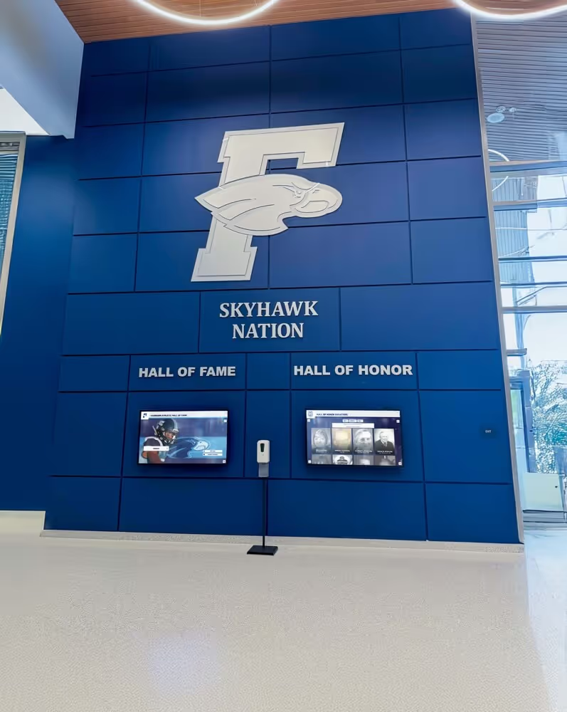
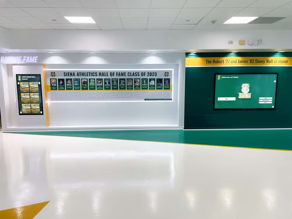
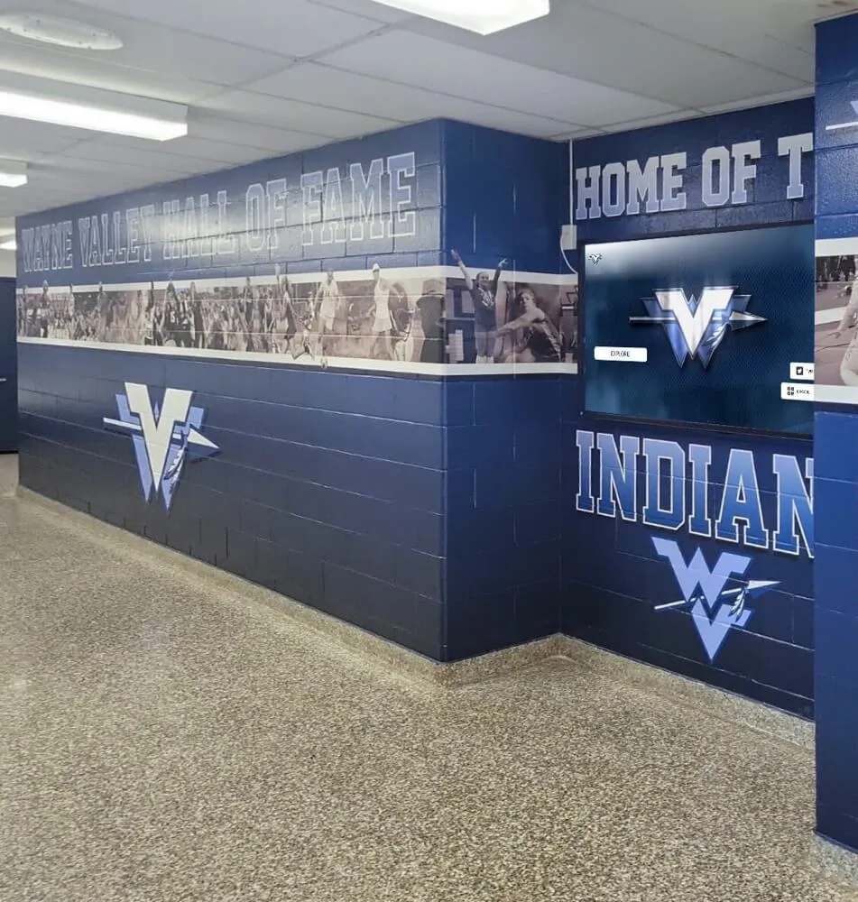
Recognition kiosks installed near trophy cases frequently share switch infrastructure with AV equipment, security cameras, and other devices — private VLAN isolation prevents lateral traffic between these endpoints while preserving upstream connectivity through the promiscuous uplink
The Private VLAN Isolation Test: Step-by-Step
Work through these steps in sequence. Each step has a clear pass condition and a fail condition. A fail at any step indicates a misconfiguration requiring remediation before the display’s isolation posture can be considered verified.
Step 1 — Verify PVLAN Configuration on the Switch
Connect to the switch management interface via SSH and confirm that the PVLAN structure is defined as intended before running any live traffic tests.
Cisco Catalyst (IOS / IOS XE):
show vlan private-vlan
Expected output shows the primary VLAN number, the secondary VLAN type (isolated or community), and the associated secondary VLAN IDs:
Primary Secondary Type              Ports
------- --------- ----------------- ------------------------------------------
40      41        isolated          Gi1/0/18, Gi1/0/19, Gi1/0/20
40      42        community         Gi1/0/21, Gi1/0/22
Then verify the promiscuous port mapping:
show interfaces GigabitEthernet1/0/1 switchport
Look for Private-vlan: Promiscuous in the output and confirm that the primary VLAN appears in the promiscuous mapping. Also verify the display port:
show interfaces GigabitEthernet1/0/18 switchport
Look for Private-vlan: Host with the correct primary and secondary VLAN associations.
Aruba CX:
show vlan <primary-vlan-id> private-vlan
show interface <port-id> | include private
Pass condition: The primary VLAN, isolated secondary VLAN, and promiscuous port mapping are all present and match the intended design. Display ports show as PVLAN host ports with correct secondary VLAN assignment.
Fail condition: The secondary VLAN is missing from the PVLAN table, the port shows as a standard access or trunk port without PVLAN mode, or the promiscuous mapping is absent. Document the discrepancy before proceeding — later connectivity tests will produce failures that look like network problems but are actually configuration gaps.
Step 2 — Test Peer Isolation (Kiosk-to-Kiosk Connectivity)
This step verifies the core guarantee of the PVLAN architecture. A correctly configured isolated secondary VLAN prevents any device in that VLAN from exchanging Layer 2 traffic with any other isolated port — even ports in the same IP subnet.
Test procedure:
- Connect a test endpoint (laptop or Raspberry Pi) to a spare switch port configured in the same isolated secondary VLAN as a recognition display. Assign it an IP address in the same subnet as the display.
- From the test endpoint, attempt to ping the recognition display’s IP address:
ping <display-IP-address> -c 4
- From the test endpoint, attempt to ping any other device in the isolated secondary VLAN on the same switch.
- From the test endpoint, attempt to ping the default gateway (the promiscuous port uplink IP):
ping <gateway-IP> -c 4
Pass condition:
- Pings to the recognition display IP: no reply — the switch does not forward ICMP between isolated ports
- Pings to other isolated VLAN peers: no reply
- Pings to the default gateway: replies received — the promiscuous uplink is correctly reachable
Fail condition: If the test endpoint receives replies from the recognition display or from peer isolated ports, PVLAN isolation is not functioning. The most common cause is a port configured as a standard VLAN access port rather than a PVLAN host port. A secondary cause is the isolated secondary VLAN not being correctly associated with the primary VLAN in the VLAN database.
Note the logic carefully: the absence of ping replies between isolated ports is the expected and correct result. Receiving replies between isolated ports means isolation is broken. Receiving no reply to the gateway ping means the promiscuous mapping is broken.
Step 3 — Verify Promiscuous Port Uplink Connectivity
The promiscuous port is the only Layer 2 path out of the isolated secondary VLAN. This step confirms that the router or Layer 3 interface associated with the primary VLAN is reachable from the recognition display.
From the test endpoint (in the isolated secondary VLAN):
ping <default-gateway-IP> -c 10
traceroute <upstream-management-IP>
From the recognition display itself — if the display operating system provides a shell or if the CMS platform includes a network diagnostics panel:
- Navigate to the display’s network diagnostics interface.
- Run a connectivity check to the default gateway IP.
- Confirm the displayed route shows a single hop to the gateway before reaching the upstream network.
Pass condition: The default gateway responds to pings from the isolated port. Traceroute shows one hop to the gateway before the upstream network becomes visible.
Fail condition: No response from the default gateway. Check that the promiscuous port mapping includes the isolated secondary VLAN ID, that the primary VLAN is active on the Layer 3 interface, and that the Layer 3 interface itself has an IP address in the display subnet.
Step 4 — Confirm DHCP, DNS, and NTP Reachability
Recognition displays require three infrastructure services to operate reliably: DHCP to obtain or renew their IP address lease, DNS to resolve CMS platform hostnames and media delivery CDN endpoints, and NTP to maintain correct system time for content scheduling, certificate validation, and log timestamps.
PVLAN configurations that pass Steps 2 and 3 can still silently break DHCP if the DHCP relay agent is configured on the secondary VLAN SVI rather than on the primary VLAN SVI. This error does not appear until the first DHCP lease renewal — typically days after initial deployment.
DHCP verification:
Release and renew the display’s DHCP lease where the operating system permits:
# Linux-based display OS
sudo dhclient -r eth0 && sudo dhclient eth0
Confirm that the display receives a lease in the expected IP range within 10–15 seconds. If the display returns a 169.254.x.x APIPA address or fails to obtain a lease, verify that:
- A DHCP relay agent (
ip helper-addresson Cisco,dhcp-relayon Aruba) is configured on the Layer 3 interface for the primary VLAN — not the secondary VLAN, which does not have its own SVI in a standard PVLAN deployment. - The DHCP server scope covers the primary VLAN subnet and does not restrict allocations based on VLAN tags that differ from the primary VLAN ID.
DNS verification:
nslookup <cms-hostname> <dns-server-IP>
dig @<dns-server-IP> <cms-hostname>
Confirm that forward lookups resolve to the expected IP addresses for the CMS platform and content delivery endpoints.
NTP verification:
ntpdate -q <ntp-server-IP>
Or check the display’s system clock synchronization status through the CMS diagnostics panel if direct shell access is not available.
Pass condition: DHCP lease obtained in the expected subnet, DNS queries resolve correctly, NTP synchronization shows an active offset of less than one second.
Fail condition: Any of the three services fails. Address DHCP relay configuration before concluding the test — a missing or misplaced relay is the single most common PVLAN deployment error that does not affect ping connectivity but prevents the display from maintaining its address assignment across reboots.
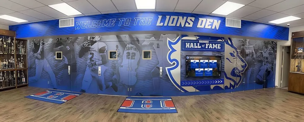
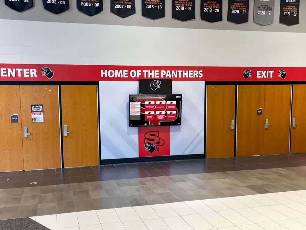
Campus lobby kiosks serving daily visitors depend on reliable upstream connectivity through the PVLAN promiscuous port — a broken DHCP relay or DNS failure produces content delivery gaps that are difficult to distinguish from CMS platform issues without a structured isolation test
Step 5 — Test CMS and Content Delivery Connectivity
The recognition display must reach the content management system over TCP to retrieve content updates, report heartbeat status, and download media assets. This step confirms that the PVLAN configuration does not block the specific ports and hostnames the CMS platform uses.
CMS connectivity check:
From the test endpoint in the isolated secondary VLAN, or from the display’s diagnostics interface:
curl -v https://<cms-hostname>/api/health
Or use a TCP connection test if curl is not available:
nc -zv <cms-hostname> 443
Content delivery CDN check:
Many recognition platforms deliver media assets through CDN hostnames separate from the CMS API endpoint. Check the platform’s network documentation for the complete list of required outbound destinations and test each:
nc -zv <cdn-hostname> 443
Pass condition: TCP connections succeed to all required CMS and CDN destinations within the expected timeframe. The display’s CMS diagnostic panel shows a connected or online status with a recent heartbeat timestamp.
Fail condition: TCP connections to CMS or CDN hosts time out or are refused. Before concluding that the PVLAN is the problem, verify:
- DNS resolution for CMS and CDN hostnames returns valid addresses (Step 4).
- The upstream firewall or ACL is not blocking outbound TCP 443 from the display subnet.
- The promiscuous port uplink routes traffic to the internet and not only to the internal management network.
Recognition display platforms that deliver athletic archive content and hall of fame programs depend on reliable outbound connectivity to media CDNs for video and image delivery — a PVLAN configuration that passes the ping test but blocks CDN traffic produces content gaps that appear to be platform reliability problems rather than network configuration failures.
Step 6 — Validate Management Access from Admin VLAN
The IT team’s management workstation (on a separate management VLAN) must be able to reach the recognition display for remote administration — CMS configuration updates, firmware management, and diagnostics access. This connectivity flows through the router, not through the PVLAN layer, making it dependent on correct routing entries and any ACLs on the routing boundary.
From the management workstation:
ping <display-IP-address>
ssh admin@<display-IP-address>
From the CMS administration dashboard:
Confirm that the display is checking in with a recent timestamp. A display that passes Steps 1 through 5 but fails Step 6 typically has one of three problems: the router is missing a route from the management VLAN to the primary VLAN subnet, an ACL on the routed interface is blocking inbound traffic from the management subnet, or a host-based firewall on the display OS is blocking SSH from unauthorized source addresses.
Pass condition: Management workstation can ping and SSH to the display. CMS shows a heartbeat timestamp within the expected check-in interval.
Fail condition: Management workstation cannot reach the display IP despite the display having outbound connectivity. Document which direction fails (inbound to display versus outbound from display) — asymmetric routing or asymmetric ACLs can produce one-way connectivity failures that are easy to overlook in a PVLAN deployment.
Common PVLAN Misconfiguration Patterns
The following table summarizes the most frequent errors observed when deploying PVLAN isolation for school recognition displays, with the symptom each produces and the corrective action:
| Misconfiguration | Symptom | Resolution |
|---|---|---|
| Display port configured as standard access port, not PVLAN host port | Peer isolation fails — display exchanges traffic with neighbors | Set switchport mode private-vlan host and assign isolated secondary VLAN |
| DHCP relay on secondary VLAN SVI instead of primary VLAN SVI | Display cannot obtain or renew DHCP lease after reboot | Move ip helper-address to the primary VLAN Layer 3 interface |
| Promiscuous port not mapped to all secondary VLANs | Isolated ports cannot reach the gateway | Add all secondary VLANs to the promiscuous mapping: switchport private-vlan mapping <primary> add <secondary-list> |
| PVLAN definitions missing on distribution or core switch | Isolation works at access layer; breaks at distribution where trunks carry secondary VLANs | Extend PVLAN definitions to all switches in the path, or use PVLAN translation at the distribution boundary |
| STP portfast not set on isolated host ports | 15–30 second STP convergence delay on each display reboot before CMS connectivity restores | Add spanning-tree portfast to isolated host ports combined with BPDU Guard |
| Secondary VLAN ID not allowed on trunk uplink | Secondary VLAN traffic stripped at trunk; display loses connectivity entirely | Add isolated secondary VLAN ID to allowed VLAN list on all trunk links in the path |
| ACL on routed interface blocking display subnet outbound | CMS connectivity works from test endpoints on other VLANs but not from display | Review ACLs on primary VLAN Layer 3 interface; permit TCP 443 and DNS outbound from display subnet |
| PVLAN not supported by switch model | Configuration appears to save but does not enforce isolation | Verify PVLAN feature support in switch documentation; migrate to a supported platform or use port isolation as an alternative |
PVLAN vs. Standard VLAN Segmentation: Comparison Table
| Feature | Standard VLAN Segmentation | Private VLAN Isolation |
|---|---|---|
| Peer traffic blocked within segment | No — all ports in the VLAN exchange traffic freely | Yes — isolated ports cannot reach each other at Layer 2 |
| Firewall required for peer block | Yes — ACL or policy at routing boundary | No — enforcement is at switch hardware layer |
| Single IP subnet for all isolated devices | No — separate VLANs typically require separate subnets | Yes — all isolated ports can share the primary VLAN subnet |
| DHCP complexity | One scope per VLAN, relay straightforward | One scope per primary VLAN; relay must target primary VLAN SVI specifically |
| Switch hardware requirement | Any managed switch | Managed switch with PVLAN feature support |
| Broadcast containment | Within VLAN | Peer isolated port broadcasts blocked; only promiscuous port broadcasts reach isolated ports |
| ARP spoofing protection | No — any peer can broadcast gratuitous ARP | Yes — gratuitous ARP from isolated peers does not reach other isolated ports |
| Audit documentation | VLAN table and firewall ruleset | PVLAN table and switch port configuration |
Digital display installations in school environments handling community recognition content — donor records, scholarship archives, student athlete profiles — benefit from PVLAN isolation not only as a security control but as a documented demonstration to school boards and community stakeholders that public-facing display infrastructure is treated with the same care applied to administrative systems.
Practical Q&A
Q: Our switches are consumer-grade managed switches that do not support PVLANs. What are the alternatives?
Many SMB and prosumer managed switches support port isolation — a feature that prevents direct Layer 2 forwarding between specific ports while allowing all ports to reach a designated uplink. Check your switch documentation for “port isolation,” “protected ports,” or “port-based VLAN isolation.” The behavior is similar to PVLAN isolation for devices on the same physical switch, though it typically does not carry the full 802.1Q PVLAN framing that enterprise switches use, which can limit interoperability across trunks to neighboring switches.
Q: Can we use PVLAN isolation for both the wired recognition kiosk and a nearby wireless access point providing guest Wi-Fi?
Yes, but the wireless access point requires different handling. A wired kiosk port can be placed directly in an isolated secondary VLAN. A wireless AP connected via a trunk port maps each SSID to a separate VLAN — the guest SSID VLAN should be isolated from the recognition display VLAN at the Layer 3 routing boundary rather than at the PVLAN layer, because the AP trunk port must carry multiple VLANs simultaneously and cannot operate as a PVLAN isolated host port. Use PVLAN isolation for wired display ports and standard inter-VLAN routing with firewall ACLs to keep the guest wireless VLAN separated from both the display VLAN and the campus administrative network.
Q: The recognition display CMS requires inbound connections from a specific cloud management IP range. Does PVLAN isolation block those inbound connections?
No. PVLAN isolation blocks lateral Layer 2 traffic between isolated ports on the same switch. Traffic originating from the internet — including inbound connections from cloud management platforms — travels through the router and enters the isolated port through the promiscuous uplink. If inbound connections from specific cloud IPs are failing, the issue is an ACL or firewall policy at the routing boundary, not the PVLAN layer.
Q: We have recognition displays in three buildings connected by fiber uplinks. Does PVLAN need to be configured on every switch in the path?
Yes. The isolated secondary VLAN ID must be defined and allowed on every switch that carries the traffic, including distribution and core switches. On transit switches that do not host PVLAN ports, you define the secondary VLAN and allow it on trunk links without configuring any PVLAN host ports. Alternatively, some network designs use PVLAN-to-VLAN translation at the distribution layer — converting the secondary VLAN to a standard routed VLAN at the building boundary — which simplifies the distribution and core configuration at the cost of somewhat more complex VLAN documentation. Recognition programs deployed across multiple school locations should document the PVLAN topology and translation points explicitly so that future network changes don’t inadvertently remove isolation at a transit switch.
Q: How often should we re-run the PVLAN isolation test?
Run the full test after initial PVLAN deployment, after any switch firmware upgrade that touches VLAN handling, after adding new recognition displays or relocating existing ones to different switch ports, and after any infrastructure change affecting VLAN or routing configuration. For ongoing assurance between formal tests, monitor the switch VLAN database for unexpected configuration drift and review CMS check-in logs — a display that suddenly stops reporting heartbeats may have had its port reconfigured during unrelated switch work.
Q: Our recognition platform vendor says their system works on a flat network. Should we still implement PVLAN isolation?
The display platform’s flat-network compatibility is a statement about its ability to function without PVLAN — not a recommendation against isolation. A display that works on a flat network also works behind a PVLAN isolated port as long as the promiscuous uplink provides the connectivity the platform requires. Platform compatibility with flat networks and district policy requiring PVLAN isolation are not in conflict.
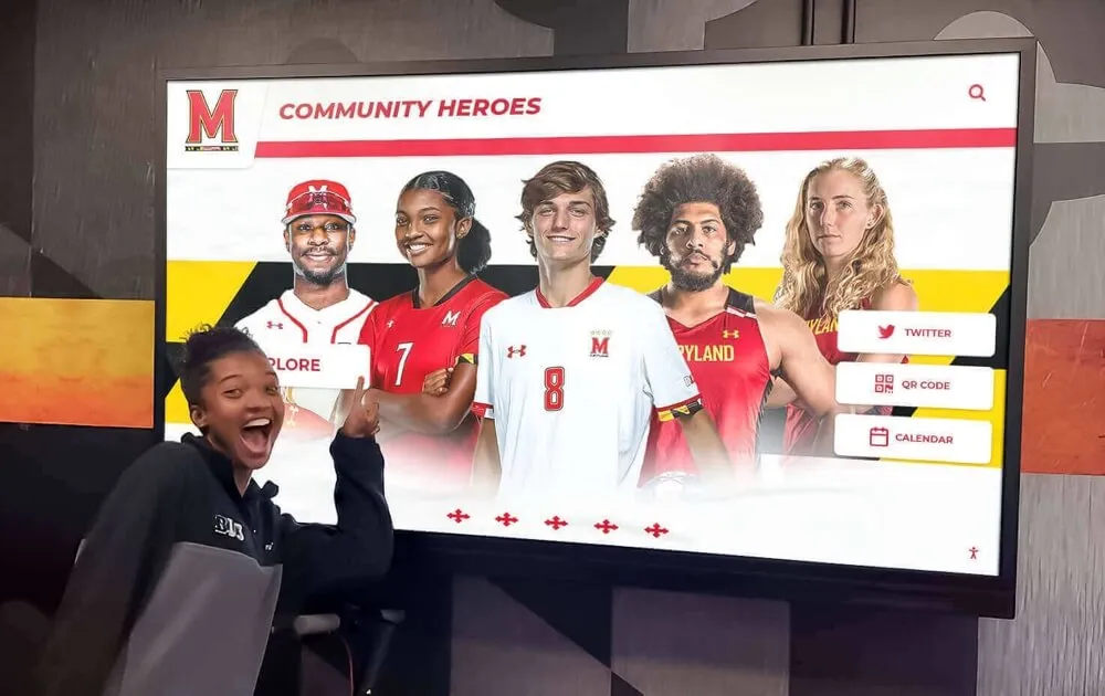
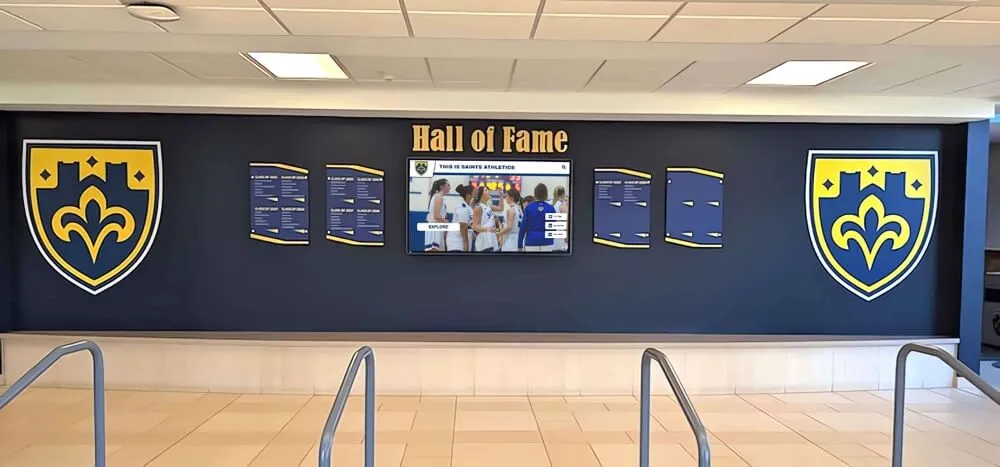
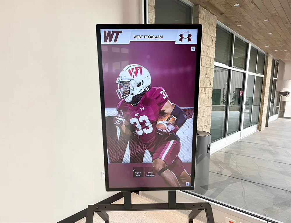
School hallway recognition kiosks depend on PVLAN isolation to stay protected from neighboring devices while continuously delivering athletic history and community recognition content to students and visitors throughout the school day
PVLAN Isolation and Recognition Platform Selection
When evaluating recognition display platforms for shared school network environments, the PVLAN isolation test reveals which platforms make network-friendly architectural choices and which create avoidable complexity:
Outbound-only CMS architecture: Platforms that initiate all CMS connections outbound from the display to the cloud require only that the promiscuous port route traffic to the internet. They do not require inbound firewall rules or routing exceptions for management traffic, which simplifies the PVLAN configuration and reduces the scope of ACLs needed at the routing boundary.
Static IP support: PVLAN-isolated displays that support static IP address assignment avoid DHCP relay complexity. Static assignments are pinned to the primary VLAN subnet directly in the display OS, eliminating the dependency on a correctly configured DHCP relay for address renewal after every reboot.
Published connectivity requirements: Well-maintained recognition platforms document their outbound hostname and port requirements explicitly, allowing network administrators to configure firewall policies and test connectivity against a defined list rather than discovering undocumented destinations through trial and error after deployment.
Diagnostics transparency: A CMS platform that surfaces check-in timestamps, connectivity status, and recent error logs in its administration dashboard allows IT teams to confirm that PVLAN configuration changes are producing the intended result without requiring direct shell access to the display for each verification step.
Evaluating display platforms against network architecture criteria before deployment prevents the common scenario where a platform designed for simple flat networks creates unexpected PVLAN integration work after the installation date has been set and the recognition program launch has been announced to families.
See How the Platform Handles Your Network Environment
Rocket Alumni Solutions recognition displays are designed for shared school network environments — with outbound-only CMS architecture, clear connectivity documentation for PVLAN and firewall configuration, and a diagnostics panel that makes network-layer troubleshooting visible to IT teams without requiring display-side shell access.
Request a Platform DemoIsolation Test Results Summary
| Test Step | Pass Result | Fail Indicates |
|---|---|---|
| Step 1: PVLAN configuration | Secondary VLAN and promiscuous mapping present | Missing PVLAN definition — reconfigure before further testing |
| Step 2: Peer isolation | No response from isolated peers | Standard VLAN mode on port — set PVLAN host mode |
| Step 3: Promiscuous uplink | Gateway responds from isolated port | Broken promiscuous mapping — check primary-secondary association |
| Step 4: DHCP / DNS / NTP | All three services reachable | DHCP relay on wrong SVI; DNS or NTP blocked by ACL |
| Step 5: CMS connectivity | CMS shows connected status with recent heartbeat | Firewall blocking outbound ports; DNS resolution failure |
| Step 6: Management access | Admin workstation reaches display IP | Missing inter-VLAN route; management ACL blocking display subnet |
A display that passes all six steps is correctly isolated at the PVLAN layer, reachable from the management network, and capable of sustaining the CMS connections needed to deliver recognition content continuously. Running this test before go-live and after any significant infrastructure change keeps the recognition program’s network posture documented and verified rather than assumed.
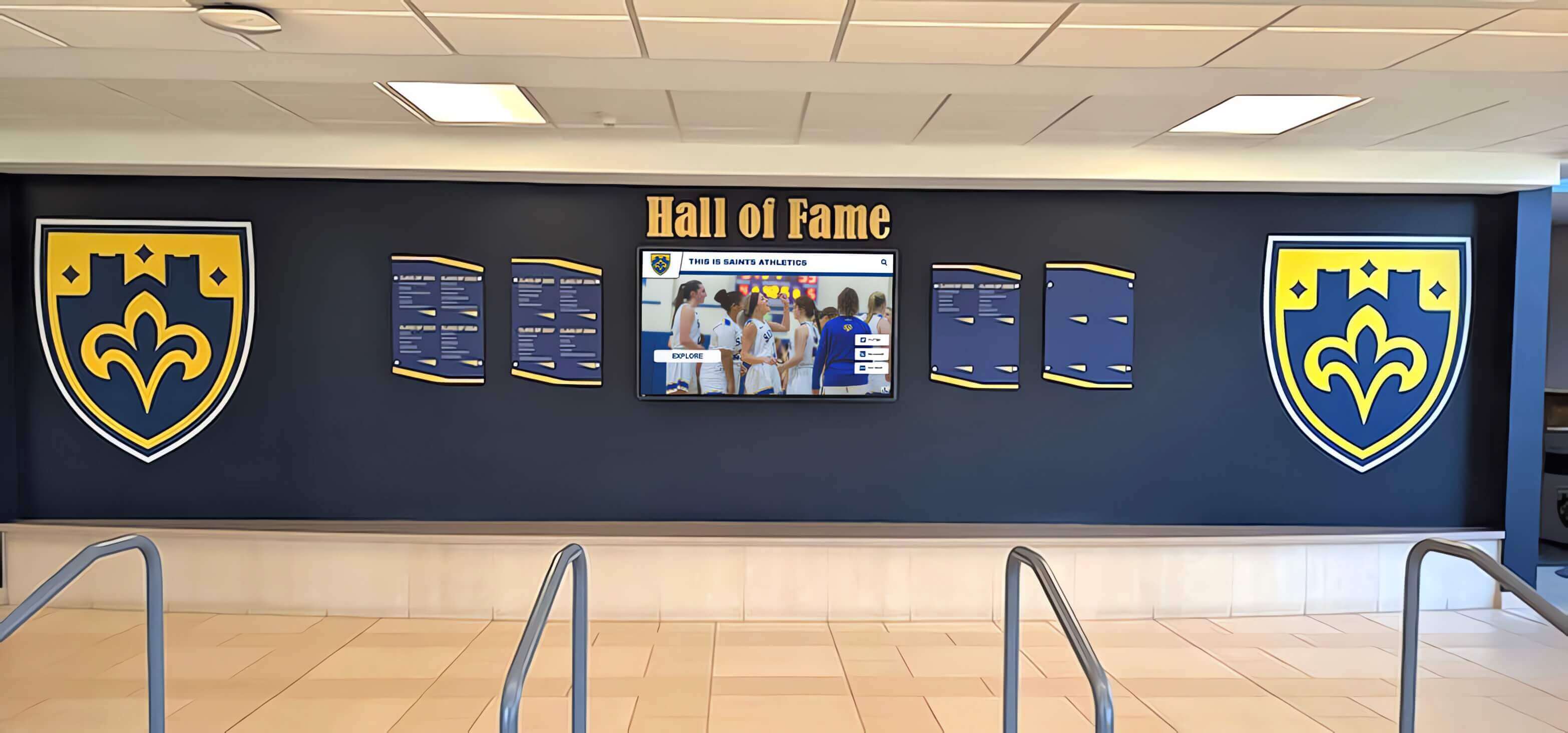
When recognition displays pass a complete PVLAN isolation test, athletic directors and IT teams can both be confident — the network security posture is verified and the recognition content delivery architecture is sound for the entire program lifecycle
For school IT and recognition program teams ready to deploy a recognition platform built for the network realities of shared campus infrastructure, the Rocket Alumni Solutions platform demo walks through connectivity requirements, PVLAN compatibility, and the CMS diagnostics tools that support exactly the structured isolation testing described in this guide.
Related resources: athletic hall of fame display software buyer’s guide for school programs — athletic recognition eligibility and display policies — digital hall of fame high contrast accessibility testing — athletic archive video workflow for school recognition programs