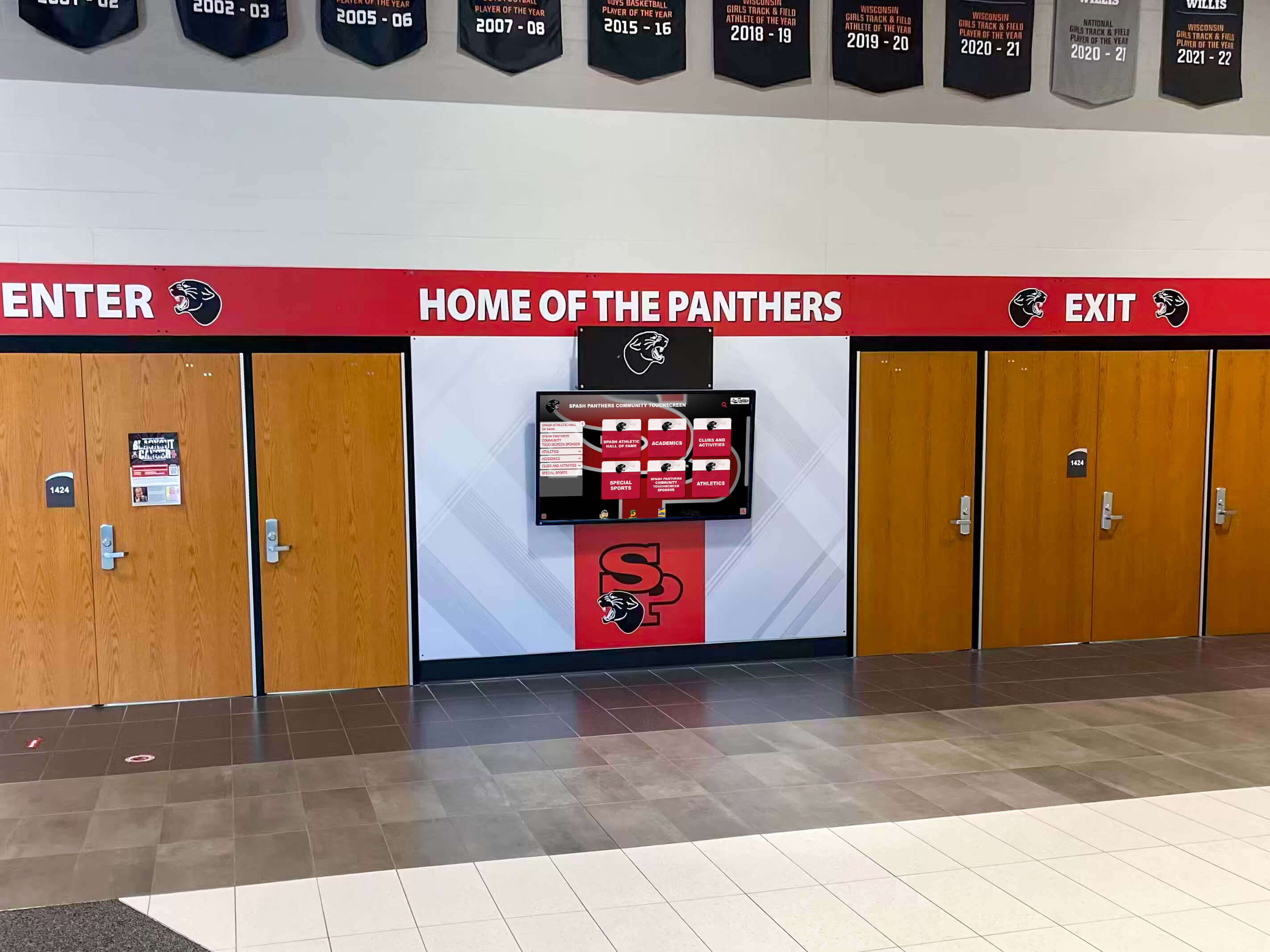
Intent: decide — A lobby kiosk that shows championship banners in the morning and a blank screen at noon has not lost power and is not running buggy software. It has experienced a link-flap event: its Ethernet port cycled between connected and disconnected — possibly dozens of times in a few seconds — disrupting every active TCP session, clearing the local ARP cache, and forcing the content management system to close and reopen its delivery connection. The display comes back on its own, the content catches up, and the problem looks like a glitch. It happens again three days later. It happens again during senior night. Each event is brief, each recovery looks clean, and none of them generate a support ticket specific enough to diagnose.
This school recognition display link flap detection checklist walks IT coordinators, AV technicians, athletic directors, and facilities staff through a structured process for identifying unstable Ethernet links before they interrupt lobby or gym recognition display experiences. The steps cover how to read switch interface counters, how to interpret flap history in syslog and event logs, how to isolate whether the problem is cable, connector, switch port, or STP topology, and how to apply port stabilization settings that prevent brief physical disturbances from becoming full session drops.
Link flapping is one of the most disruptive and least visible network problems for school recognition kiosks precisely because each individual event is short. The display’s Ethernet driver reports a link-up event and resumes normal operation within seconds, but every CMS connection, DNS lookup, and media delivery session that was in progress at the moment of link-down must restart from scratch. Running a systematic school recognition display link flap detection checklist takes 30–45 minutes and identifies whether a flapping link — not a failing display or a CMS platform issue — is the root cause of intermittent content delivery failures.

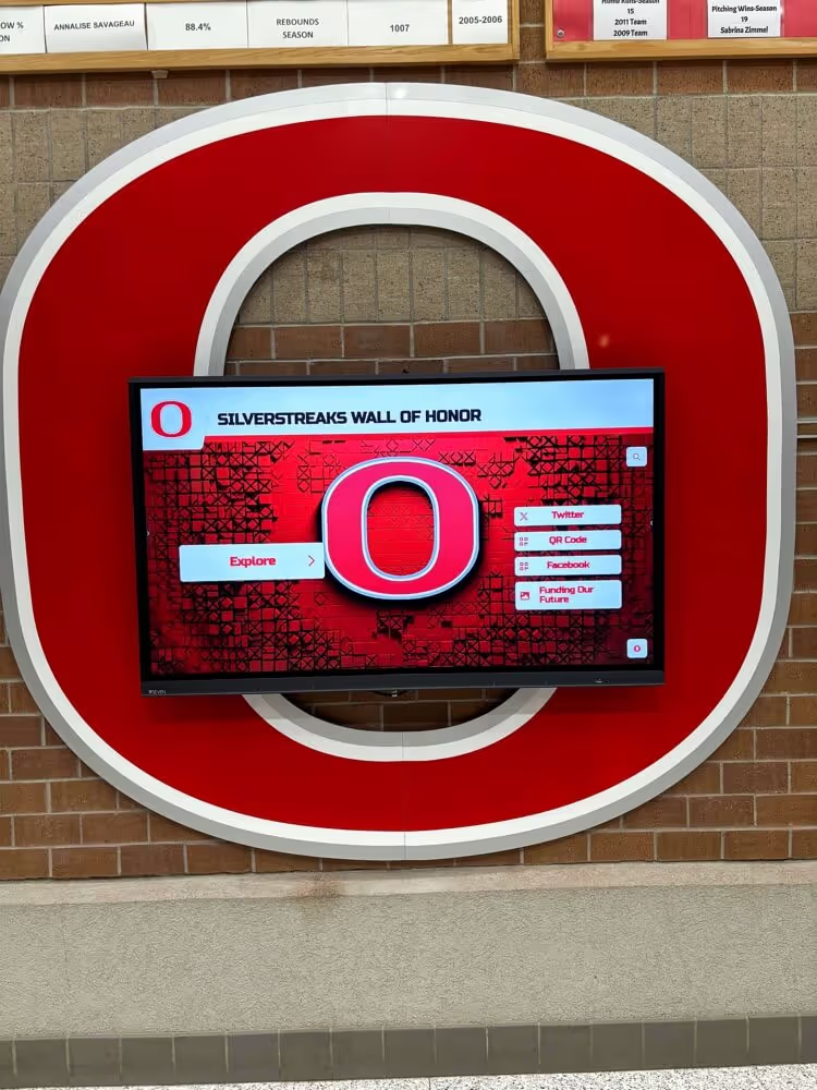
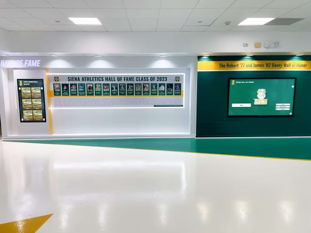
Lobby recognition displays cycling content through a school day generate thousands of CMS sessions — a link-flap event resets every active session simultaneously and produces brief content gaps that accumulate into noticeable reliability problems over weeks
What Link Flapping Is and Why It Affects Recognition Displays
An Ethernet link is described as “up” when the physical layer detects a valid signal at both ends of the cable — the switch port and the display’s NIC — and the auto-negotiation handshake has produced a matched speed and duplex setting. A link flap occurs when this up state collapses to a link-down state and then returns to link-up, typically within milliseconds to a few seconds. Switches record each transition as a discrete event.
For a recognition display, the consequences of a link flap extend beyond the physical layer:
- Active TCP sessions drop. The display’s connections to the CMS platform, image delivery CDN, DNS resolver, and NTP server all terminate. Each must complete a fresh three-way handshake before content delivery resumes.
- ARP cache entries age or flush. The display’s local ARP table may lose its gateway MAC address entry, requiring a new ARP broadcast before the first packet can leave the subnet.
- Spanning Tree Protocol reconverges. If the switch port is not configured as an STP edge port, a link-down event triggers an STP topology change notification. Other switches in the broadcast domain flush their MAC address tables, briefly forwarding unknown unicast frames as floods — a short period of degraded performance affecting all devices on the VLAN, not just the display.
- DHCP leases may not renew cleanly. If the link-down event occurs near a DHCP lease renewal, the display may briefly attempt to renew from an address that the DHCP server has already reclaimed.
The combination means that a link flap lasting half a second produces content delivery failures that take 10–30 seconds to recover — long enough to be noticed during an assembly, an awards ceremony, or a busy morning arrival period when the most visitors walk past the display.
Digital hall of fame programs that rely on live CMS connections to deliver updated athlete records, senior tributes, and booster recognition panels are the most sensitive to link-flap events because they depend on persistent connections rather than cached static content.
Common Causes of Link Flapping in School Recognition Display Environments
Understanding why link flapping occurs in school environments helps target the checklist steps at the most likely root cause:
| Root Cause | How It Produces a Flap | Environments Where Most Common |
|---|---|---|
| Faulty or aging patch cable | Physical wire breaks or crimped conductor intermittently loses continuity | Displays in high-traffic corridors or near equipment closet doors |
| Damaged RJ-45 connector | Bent, corroded, or incompletely seated connector loses signal when disturbed | Displays moved for cleaning or events; cables flexed repeatedly |
| Failing switch port transceiver | Switch port NIC degrades and loses signal detection reliability | Older switches with high port-hour counts |
| PoE negotiation failure | Power-over-Ethernet renegotiation cycle powers off and restores the link | Any PoE-powered display or PoE-powered switch attached to the same injector |
| STP BPDU Guard triggering error-disable | A BPDU received on an edge port shuts the port down; errdisable recovery restores it | Displays connected through unmanaged switches or PoE hubs that forward BPDUs |
| Carrier-delay too short | Switch brings link up before the physical layer has fully stabilized, then detects a transient and goes down again | Managed switches with default or zero carrier-delay settings |
| Vibration or mechanical disturbance | Nearby HVAC, locker impact, or equipment cart movement shifts cable connectors | Gym-mounted displays; displays in locker room corridors |
| Cable length exceeding spec | Cat5e at Gigabit speed degrades beyond 55 m run length; Cat6 near 100 m boundary | Displays on the far end of long in-wall cable runs |
School recognition kiosks installed for athletic recognition and booster club visibility are often located in gyms and corridors — exactly the environments where vibration, cable flexing, and long cable runs are most common.
Before You Begin: What to Gather
Collect the following before accessing switch management interfaces:
- Switch make, model, and firmware version — command syntax for interface counters, syslog output, and port stabilization settings differs between Cisco IOS, Cisco IOS XE, HP/Aruba ProCurve, Aruba CX, Juniper EX, Netgear, and Ubiquiti UniFi.
- Switch port number serving the recognition display — the specific physical port the display’s Ethernet cable terminates on. Trace the patch cable at the wiring closet if the port label is not on the cable itself.
- Display device hostname or IP address — used to cross-reference MAC address table entries and DHCP lease records with the correct switch port.
- Switch management access — read-only access is sufficient for Steps 1 through 4. Write access is required in Steps 5 and 6 to apply stabilization settings.
- Access to switch syslog output or a syslog server — required for Step 2 to review the flap history with timestamps.
- A spare patch cable and RJ-45 tester or cable certifier — needed in Step 4 to rule out cable-layer faults without pulling in-wall cabling.
- A small flat-head screwdriver — to reseat RJ-45 connectors without twisting the cable, which can itself cause a flap during inspection.
Recognition Display Link Flap Detection Checklist: Numbered Steps
Work through these steps in order. Each step produces a clear pass or fail result indicating whether the flapping source is physical, STP-related, PoE-related, or configuration-related.
Step 1 — Read Interface Flap Counters on the Switch
Every managed switch maintains per-port counters that increment each time the link state changes. Reading these counters establishes whether flapping has occurred and how frequently, before any other investigation.
Cisco Catalyst switches (IOS / IOS XE):
show interfaces GigabitEthernet1/0/12
Look for the Last input and Last output timestamps — a very recent timestamp combined with a high input errors count indicates recent activity that may include flap events. More directly, look for the line:
5 minute input rate 0 bits/sec, 0 packets/sec
If this line shows zero while the display should be actively delivering content, the link has been down or severely degraded recently.
To see flap count specifically:
show interfaces GigabitEthernet1/0/12 | include flap
On IOS XE platforms that support it:
show interfaces GigabitEthernet1/0/12 counters errors
Check the Link-Flaps field. A non-zero value since the last counter reset confirms flapping has occurred on this port.
HP / Aruba ProCurve:
show interfaces 12
Look for the Port Status field transitions and check Rx-Error and Tx-Error counters. On ProCurve platforms, interface event history is more accessible via syslog than via CLI counters directly.
Aruba CX (ArubaOS-CX):
show interface 1/1/12
show interface 1/1/12 counters
The link_change_counter field shows how many times the port has transitioned since boot or last counter clear.
Juniper EX Series:
show interfaces ge-0/0/12 extensive
Look for the Link transitions counter under the physical interface statistics. A link transitions value above zero since last system boot indicates flapping has occurred.
Ubiquiti UniFi:
Interface-level flap counters are not accessible in the standard UniFi GUI. Use SSH to the UniFi switch and run:
swctrl port show 12
Or check the switch’s local log for interface down/up events:
cat /var/log/messages | grep -i "link\|down\|up" | grep "Port 12"
Result interpretation:
- Zero flap count or link transitions since last reboot: pass. Link flapping is not the current cause of display failures. Investigate content platform or display software instead.
- Non-zero flap count with recent timestamps: fail. Proceed through remaining steps to isolate the cause.
Step 2 — Review Syslog for Link-Down Events with Timestamps
Flap counters show how many events occurred but not when. Syslog timestamps reveal whether flapping correlates with specific times — arrival periods, lunch, after-hours cleaning, HVAC cycling — that help identify the trigger.
Cisco IOS / IOS XE — review local syslog buffer:
show logging | include GigabitEthernet1/0/12
Link-down events appear as:
%LINK-3-UPDOWN: Interface GigabitEthernet1/0/12, changed state to down
%LINK-3-UPDOWN: Interface GigabitEthernet1/0/12, changed state to up
A pattern of down/up pairs within seconds of each other, repeated multiple times per day, is the definitive syslog signature of link flapping. If the events cluster between 7:00 and 8:30 AM on school days, foot traffic near the cable run or display enclosure is the likely physical trigger.
HP / Aruba ProCurve:
show log -r | include "port 12\|port12"
ProCurve logging timestamps reference the switch uptime rather than wall-clock time unless NTP is configured. Verify NTP configuration first:
show sntp
Aruba CX (ArubaOS-CX):
show events interface 1/1/12
This command returns a timestamped event history specific to the interface, including link state transitions.
Juniper EX Series:
show log messages | match "ge-0/0/12.*link\|Link"
Result interpretation:
- Syslog shows no link state change events for the display port: the flap counters may be legacy from a prior event. If display reliability is currently good, note the baseline and monitor.
- Syslog shows repeated down/up transitions: note the timestamps and frequency. Correlate with school schedule, HVAC cycles, or cleaning crew access times. Proceed to Step 3.
Step 3 — Check for STP Error-Disable Events
If a BPDU Guard or loop-guard event triggered an error-disable shutdown on the display port, the switch will restore the port after the error-disable recovery timer expires — producing a link-flap cycle on a fixed interval rather than a random one. This is distinct from physical cable flapping and requires a different fix.
Cisco IOS / IOS XE:
show interfaces status err-disabled
If the display port appears in this output, an STP event caused the port to be shut down. Check syslog for the trigger:
show logging | include BPDU\|err-disabled\|LOOP\|GigabitEthernet1/0/12
A BPDU Guard event looks like:
%SPANTREE-2-BLOCK_BPDUGUARD: Received BPDU on port GigabitEthernet1/0/12 with BPDU Guard enabled.
%PM-4-ERR_DISABLE: bpduguard error detected on Gi1/0/12, putting Gi1/0/12 in err-disable state
This event means a device connected to — or behind — the display’s switch port is sending Spanning Tree BPDU packets. On a display kiosk, this most commonly happens when the display is connected through an unmanaged switch or a PoE hub that forwards BPDUs upstream to the managed switch.
HP / Aruba ProCurve:
show spanning-tree
Check the BPDU-Protected column for the display port. A value of Yes with a Blocked state indicates BPDU protection has triggered.
Aruba CX (ArubaOS-CX):
show spanning-tree interface 1/1/12
show events interface 1/1/12 | include bpdu\|errdisable
Result interpretation:
- No error-disable events, no BPDU Guard triggers: STP is not the flap cause. Continue to Step 4.
- BPDU Guard or error-disable events present: the display port is receiving BPDUs. Remove the unmanaged switch or hub from the display’s network path, or apply a root-guard policy instead of BPDU Guard to allow STP forwarding without permitting a topology takeover. Verify the fix by rerunning this step after the change.
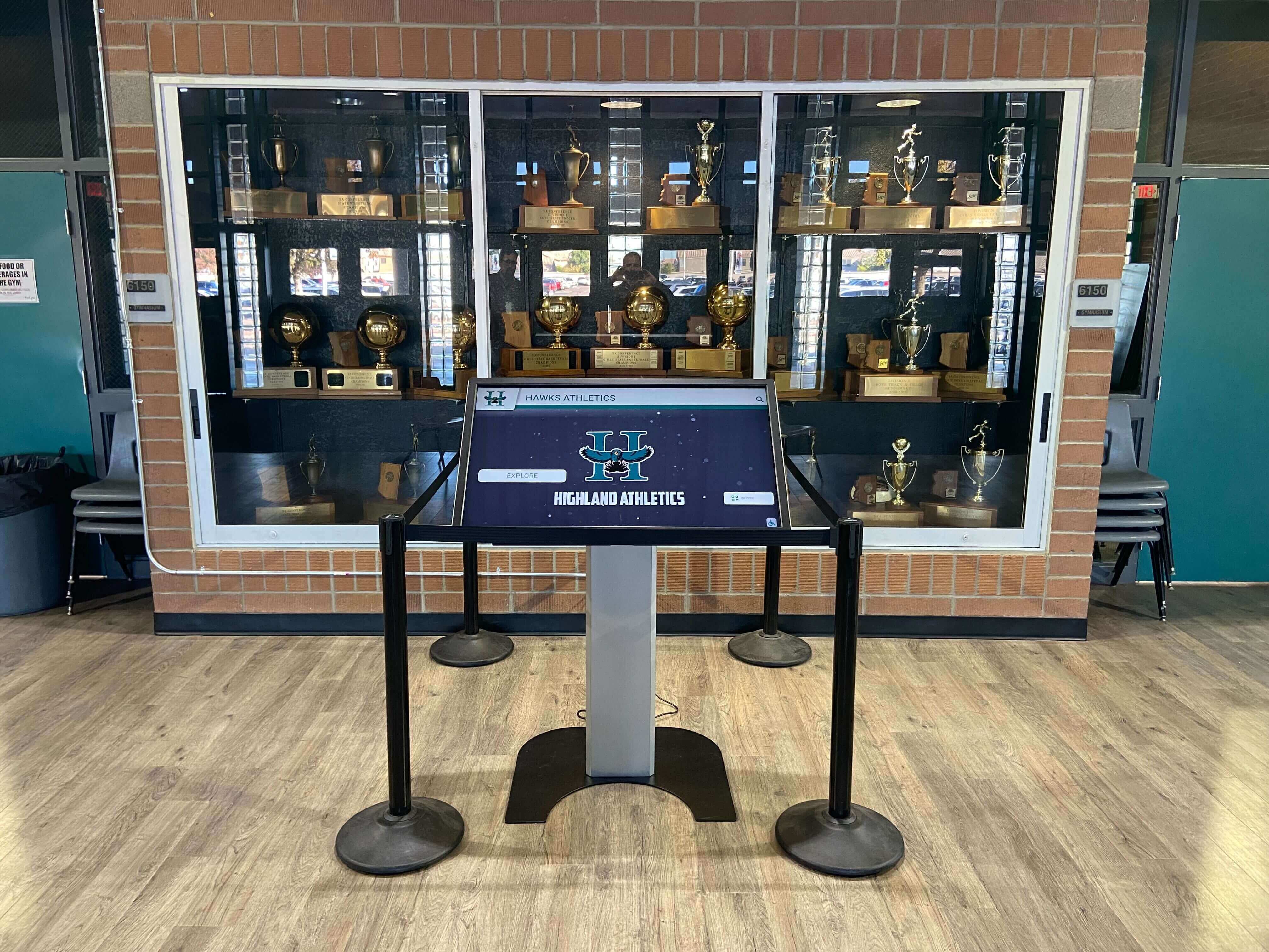
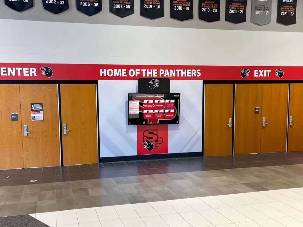
Trophy case kiosks connected through unmanaged PoE switches or hubs can trigger BPDU Guard events on the managed switch upstream — producing a regular link-flap cycle on the error-disable recovery timer
Step 4 — Test the Physical Cable and Connector
If Steps 1–3 confirm flapping is occurring but rule out STP as the cause, the fault is likely physical. Physical cable and connector testing is the most definitive step in the checklist and resolves the majority of flap problems on displays that have been installed for more than two years.
Test with a cable certifier or basic RJ-45 tester:
Disconnect the patch cable from the switch port and the display’s NIC. Connect both ends to a cable tester. A quality tester checks each wire pair for:
- Continuity (no open circuits)
- Short circuits between pairs
- Pair mapping (no crossed or split pairs)
- Length (to detect runs approaching specification limits)
A fault in any of these dimensions indicates the cable should be replaced before proceeding to software-level configuration changes.
If a cable tester is not available, substitute with a swap test:
Replace the existing patch cable at the switch end — from the wall jack to the switch port — with a known-good patch cable of the same or shorter length. Monitor the switch flap counter over the next 30 minutes. If flap events stop, the original patch cable was the fault source. This does not diagnose the cable run inside the wall, but it isolates whether the removable patch segment is the problem.
Check the RJ-45 connector seating:
At both ends of the cable — the switch port and the display NIC — inspect whether the RJ-45 connector is fully seated. The connector’s locking tab should click into place and resist a light pull. A partially seated connector can lose contact when the cable is disturbed by vibration, traffic, or thermal expansion. Remove and reseat the connector at each end and listen for the click.
Check for cable bend radius violations:
Examine the full visible cable run. Cables bent tightly around corners, caught in door frames, or pulled taut against conduit edges lose signal integrity at the bend point over time. A cable showing a visible crease or kink near a bend is a candidate for replacement regardless of whether a cable tester shows a fault — testers report current continuity, not mechanical degradation that will worsen.
Result interpretation:
- Cable tester shows a wiring fault or continuity failure: replace the cable. Retest after replacement.
- No cable fault found but swap test eliminated flapping: replace the original patch cable.
- No cable fault and swap test shows continued flapping: the fault is at the switch port or in the in-wall cable run. Proceed to Step 5.
Creative trophy case displays that incorporate live touchscreen kiosks depend on stable physical connections — periodic cable inspection as part of the school’s routine AV maintenance schedule catches connector degradation before it produces display outages.
Step 5 — Test by Moving the Display to an Adjacent Switch Port
If the patch cable passes all tests but flapping continues, the switch port itself may be failing. Moving the display’s connection to an adjacent port is the definitive switch-port isolation test.
Steps to move the connection:
- Note the current port number (e.g., GigabitEthernet1/0/12).
- Verify the adjacent port (e.g., GigabitEthernet1/0/13) is available and unoccupied.
- Before moving the cable, check the current port configuration:
Note the VLAN assignment, PoE settings, and any applied policies (QoS, RA Guard, DHCP snooping, etc.).show running-config interface GigabitEthernet1/0/12 - Apply the same configuration to the new port.
- Move the display’s patch cable from the old port to the new port.
- Verify the display connects on the new port:
The display’s MAC address should appear in the MAC table within 30 seconds.show interfaces GigabitEthernet1/0/13 show mac address-table interface GigabitEthernet1/0/13 - Monitor the new port’s flap counter over 30 minutes:
show interfaces GigabitEthernet1/0/13 | include flap
Result interpretation:
- Flapping stops on the new port: the original switch port (Gi1/0/12) is failing. Mark it out of service and open a support case with the switch vendor or schedule switch replacement if multiple ports show similar behavior.
- Flapping continues on the new port: the fault is not port-specific. The in-wall cable run, the display’s NIC, or a configuration issue affecting the entire switch is more likely. Escalate to a cabling contractor for in-wall cable certification.
Step 6 — Apply Port Stabilization Settings to Prevent Transient Flaps
Even on a healthy cable with a healthy switch port, brief physical disturbances — a door closing near the cable run, an HVAC compressor cycling, or foot traffic vibrating a suspended ceiling — can produce momentary signal loss that the switch interprets as a link-down event. Port stabilization settings add a configurable delay before the switch acts on a detected link-state change, filtering out transient events that resolve before the delay expires.
Cisco IOS / IOS XE — carrier-delay:
The carrier-delay command delays the switch’s response to link-state changes. The default on most Cisco platforms is 0 seconds for link-up and 2 seconds for link-down. Setting both to a value that filters transients without masking genuine failures — typically 2–5 seconds for link-up and 5–10 seconds for link-down — reduces nuisance flap events significantly:
interface GigabitEthernet1/0/12
 carrier-delay up msec 2000
 carrier-delay down msec 5000
exit

write memory
Ensure the port is configured as an STP edge port (PortFast):
An STP edge port does not generate topology change notifications on link-down events and does not wait through the STP listening and learning states on link-up. For a display port where no switching device is attached, PortFast is always correct and eliminates the 30-second STP convergence delay after a flap event:
interface GigabitEthernet1/0/12
 spanning-tree portfast
exit

write memory
Configure error-disable recovery if BPDU Guard is in use:
If BPDU Guard is enabled and a BPDU event does occur, the port will recover automatically after the recovery timer expires rather than requiring manual intervention:
errdisable recovery cause bpduguard
errdisable recovery interval 300
A 300-second (5-minute) recovery interval balances automatic restoration against the risk of repeatedly re-enabling a port that is receiving BPDUs from a persistent source.
HP / Aruba ProCurve:
interface 12
 spanning-tree edge-port
 link-keepalive
exit
write memory
The link-keepalive command enables a periodic signal that detects unidirectional link failures before they cause session drops.
Aruba CX (ArubaOS-CX):
interface 1/1/12
 spanning-tree port-type admin-edge
 link-debounce down 5000
 link-debounce up 2000
exit
write memory
Juniper EX Series:
set interfaces ge-0/0/12 link-down-hold-time 5000
set interfaces ge-0/0/12 link-up-hold-time 2000
set protocols rstp interface ge-0/0/12 edge
commit
Result interpretation:
- After applying stabilization settings, flap counters stop incrementing and syslog shows no further link-state change events: the transient disturbances are now filtered. Monitor for 48 hours before closing the investigation.
- Flap counters continue to increment after stabilization: the physical signal degradation is too severe for debounce filtering to mask. Return to the physical cable investigation or escalate to switch hardware replacement.
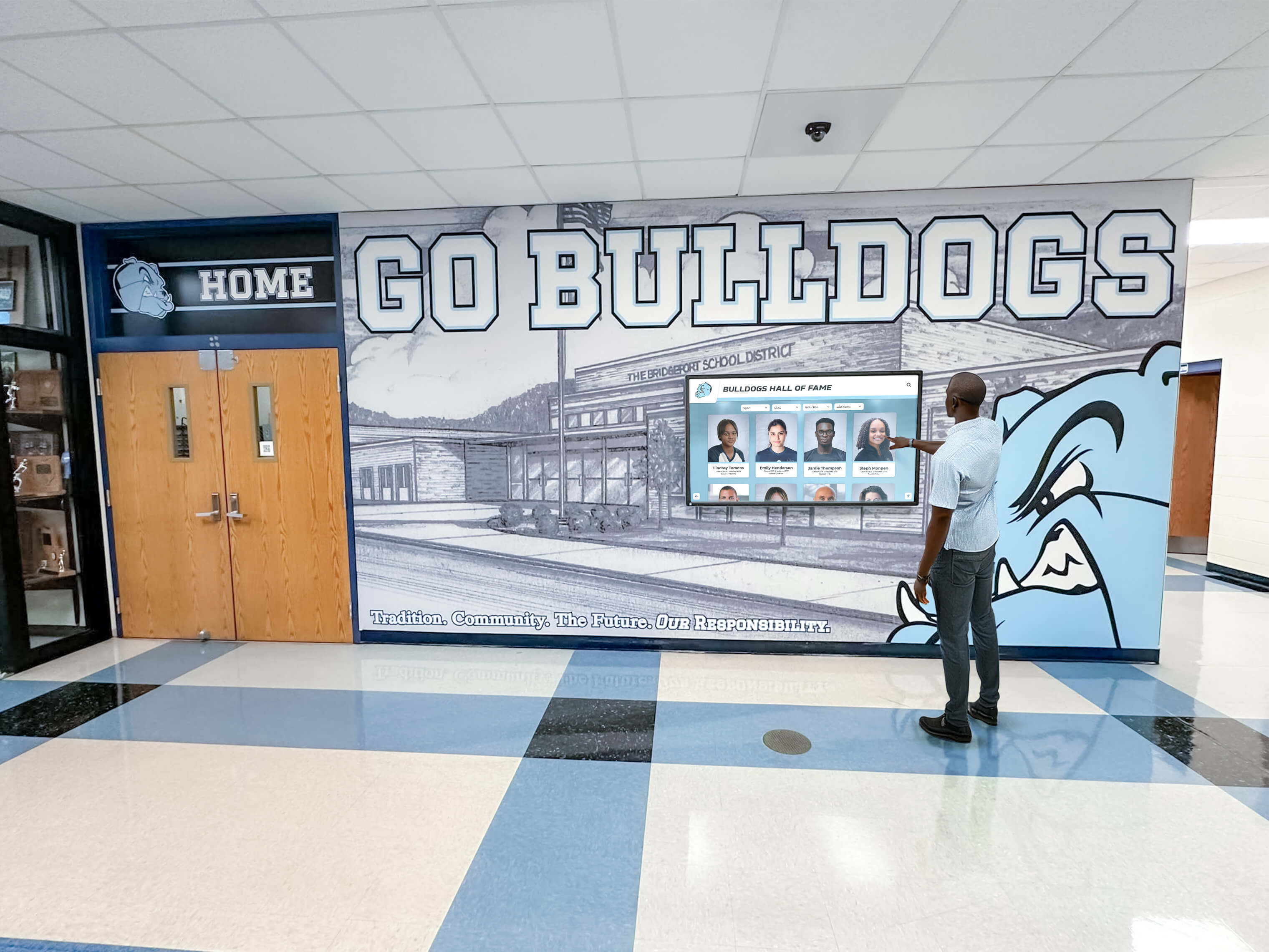
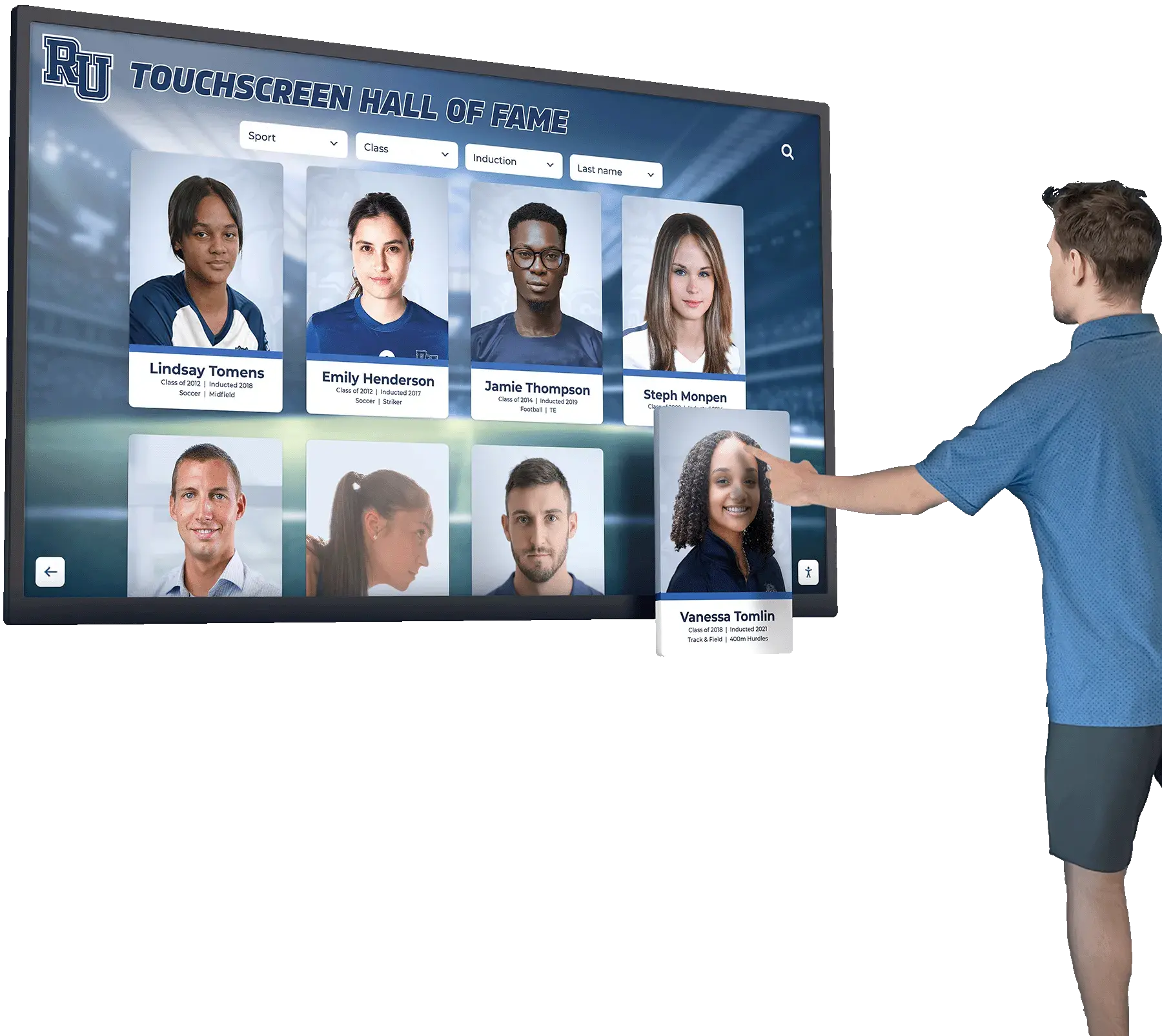
Touchscreen recognition displays that visitors interact with during school events must remain connected throughout the session — port stabilization settings prevent brief signal transients from resetting CMS sessions mid-interaction
Switch Platform Reference: Link Flap Detection and Stabilization Commands
| Switch Platform | Flap Counter Command | Syslog Review Command | Carrier Delay / Debounce | STP Edge Port |
|---|---|---|---|---|
| Cisco IOS | show interfaces Gi1/0/12 | include flap | show logging | include Gi1/0/12 | carrier-delay up/down msec | spanning-tree portfast |
| Cisco IOS XE | show interfaces Gi1/0/12 counters errors | show logging | include Gi1/0/12 | carrier-delay up/down msec | spanning-tree portfast |
| HP / Aruba ProCurve | show interfaces 12 | show log -r | include port 12 | link-keepalive | spanning-tree edge-port |
| Aruba CX (ArubaOS-CX) | show interface 1/1/12 counters | show events interface 1/1/12 | link-debounce down/up | spanning-tree port-type admin-edge |
| Juniper EX Series | show interfaces ge-0/0/12 extensive | show log messages | match ge-0/0/12 | link-down/up-hold-time | protocols rstp interface edge |
| Netgear Smart Managed | Port Statistics in GUI | System Log in GUI | Not available natively | Spanning Tree Edge in GUI |
| Ubiquiti UniFi | SSH: swctrl port show <port> | SSH: cat /var/log/messages | grep Port | Not available in GUI | Auto-detected in newer firmware |
For platforms without native carrier-delay or link-debounce support, the practical mitigation is to ensure STP PortFast or edge-port mode is configured — this eliminates the STP-related delays and MAC table flushes that amplify the content delivery impact of a link flap, even if the flap itself cannot be filtered at the physical layer.
Supplementary Link Stability Measures for Recognition Display Ports
When carrier-delay and STP edge configuration are in place, these additional measures further reduce the risk of link-flap events affecting display performance:
| Measure | How It Helps | When to Apply |
|---|---|---|
| Dedicated VLAN for recognition displays | Limits MAC table flush scope — a flap-triggered topology change only flushes MAC addresses within the display VLAN, not across the entire switch | When multiple VLANs share a switch and STP topology changes are propagating broadly |
| Static MAC address entry for the display | Prevents ARP cache invalidation from delaying the first packet after a link-up event | When DHCP-assigned addressing causes ARP delay post-flap |
| PoE class pre-negotiation | Prevents PoE renegotiation from cycling the link when a high-power display device requests more power than the default class | When the display device is PoE-powered at Class 4 or above |
| Shielded Cat6 cable (STP/FTP) on cable runs near HVAC or electrical conduit | Reduces electromagnetic interference that can degrade signal quality and trigger false link-down events | On cable runs in mechanical rooms, gym ceilings, or alongside electrical conduit |
| Cable management anchoring at connectors | Prevents mechanical vibration from flexing the cable at the connector termination — the most common point of wear | On any display where the cable is not strain-relieved at the RJ-45 entry point |
Senior night displays and athletic event recognition programs that run in gym environments — where HVAC units cycle frequently and floor vibration is continuous during events — benefit most from shielded cable and connector anchoring alongside the software stabilization settings.
Common Pitfalls When Diagnosing Recognition Display Link Flapping
Resetting counters before recording the baseline. Some IT teams clear interface counters as a first step — this erases the evidence of how many flap events have occurred and when they started. Always read and record the current counter values before clearing them. Clearing counters is appropriate only after a fix has been applied, to establish a new baseline.
Attributing flapping to the display platform without checking switch syslog. A content delivery failure that clears on its own looks like a software bug. Switch syslog entries showing changed state to down followed immediately by changed state to up on the display port redirect the diagnosis from application layer to physical layer — but only if the syslog is consulted before the display’s CMS event log.
Applying carrier-delay without verifying PoE power budget. Carrier-delay settings can delay the detection of a genuine PoE power budget exhaustion event on the switch. If the display is PoE-powered and the switch is near its PoE power budget limit, a carrier-delay setting may mask the flap caused by power cycling rather than filtering a transient. Check the switch’s PoE power consumption before applying carrier-delay:
show power inline
Ensure the available PoE budget exceeds the display’s rated power consumption by at least 20%.
Missing the unmanaged switch in the path. A display connected to an outlet on a wall plate may be wired through a small unmanaged switch in a mounted enclosure that the cabling diagram does not show. Unmanaged switches do not appear in CDP/LLDP neighbor tables and are invisible to syslog. If the managed switch shows the display’s MAC address with a normal port entry but flapping persists after cable and port tests, physically trace the entire cable path from the display to the wiring closet to identify any inline devices.
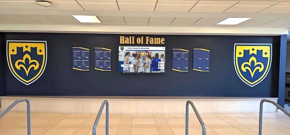
Digital hall of fame and donor wall sponsor recognition programs installed in high-profile lobby spaces are particularly exposed to cabling complexity — donor walls often involve multiple display screens, each connected through a distributed media player network with small hubs or media converters that can introduce invisible STP forwarding paths.
Applying PortFast globally instead of per-port. Enabling STP PortFast globally on a switch marks all ports as edge ports, including uplinks that connect to other switches. A BPDU arriving on an uplink configured with PortFast and BPDU Guard triggers an error-disable shutdown on the uplink — a much more serious event than a display port flap. Apply PortFast only to the specific access ports serving recognition displays and other endpoint devices, not to uplink or trunk ports.
Recognition Display Link Flap Detection Checklist Summary
Use this checklist with your network administrator during the test session. Print and complete one copy per recognition display port under investigation.
- Switch make, model, and firmware version recorded
- Display port number and VLAN confirmed — patch cable traced at both ends
- Display MAC address confirmed — from device settings or DHCP lease table
- Interface flap counter read and recorded — baseline value noted before any changes
- Syslog reviewed for link-state change events on the display port — timestamps noted
- Flap events correlated with school schedule — arrival periods, events, cleaning cycles
- STP error-disable status checked — display port not in err-disabled state
- BPDU Guard events reviewed in syslog — no BPDUs received from display port
- Patch cable tested with cable certifier or tester — no wiring faults detected
- RJ-45 connectors at both ends inspected and reseated — locking tabs engaged
- Cable bend radius inspected — no kinks or tight bends in visible run
- Swap test with known-good patch cable performed — flap behavior noted after swap
- Display moved to adjacent switch port — flap behavior compared on new port
- In-wall cable run identified as suspect if flapping continues on all ports — escalation to cabling contractor noted
- Carrier-delay or link-debounce settings applied to display port — values recorded
- STP PortFast or edge-port mode confirmed on display port — not applied to uplink ports
- Error-disable recovery configured for BPDU Guard if applicable — recovery interval set
- PoE power budget verified — display consumption within 80% of available budget
- Interface counters cleared after fix applied — new baseline established
- Syslog monitored for 48 hours after fix — no further link-state change events
- Configuration saved to non-volatile storage —
write memoryor equivalent run
When to Run the Link Flap Detection Checklist
Run the school recognition display link flap detection checklist:
- At initial display installation on any managed switch — verify counter and syslog baseline before declaring the display production-ready so any subsequent flap events are measurable against a clean starting point
- When display content delivery fails intermittently without a CMS platform error — link flapping is the most common physical-layer cause of session drops that the application layer reports as timeouts or disconnections
- After any physical move of the display or rerouting of the cable — even a carefully managed cable move can introduce a connector seating issue or a new bend point that produces flaps under vibration
- After switch replacement or port migration — the new port may have different default settings for carrier-delay, PoE class, or STP mode
- When a display in a gym or corridor reports problems only during school hours — a time-of-day pattern implicates physical disturbances (foot traffic, HVAC cycles, door movement) rather than software or CMS issues
- After any firmware update on the managed switch — firmware updates on some platforms reset carrier-delay and STP edge-port settings to factory defaults
Recognition programs tied to memorial and tribute displays in school hallways — where reliable uptime carries an added emotional weight for the community — are strong candidates for scheduled semi-annual link stability checks, not just reactive testing when a problem is reported.
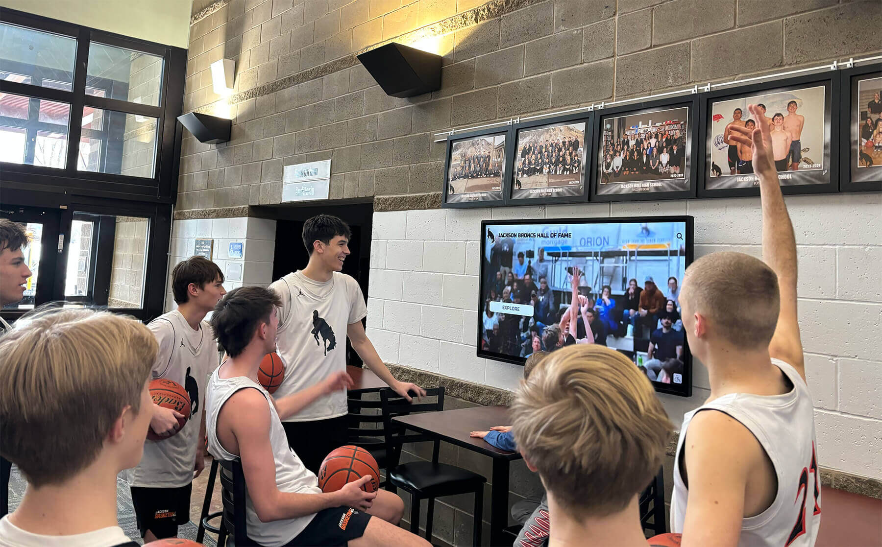
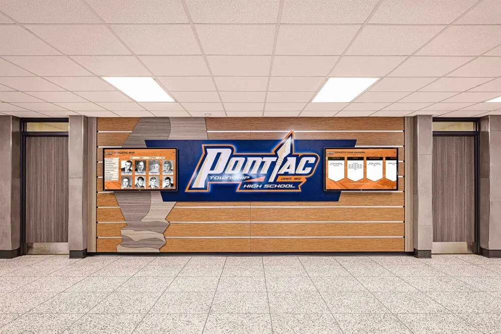
Students and visitors who gather around lobby recognition displays during school events notice every gap in content delivery — link-flap detection and port stabilization are the network foundation that keeps the recognition experience uninterrupted
Frequently Asked Questions
Q: How many link flaps per day is considered a problem for a recognition display?
Any link flap during school hours that causes a visible content gap is a problem worth investigating. From a pure networking perspective, a single unplanned link-state change on an access port serving an endpoint device indicates an underlying physical or configuration issue that will worsen over time. A display port that shows zero flap events over a 30-day period is correctly configured and physically sound.
Q: Can a recognition display’s NIC itself cause link flapping?
Yes. A display media player with a failing NIC may generate link-down events from the display side rather than from the cable or switch. The switch still records the flap event regardless of which side initiated it. Distinguish this from a cable or switch fault by connecting a known-good laptop to the same cable and switch port. If the laptop’s port shows a stable link while the display’s original port showed flapping, the display’s NIC is the suspect.
Q: Does link flapping affect touchscreen responsiveness, or only content delivery?
Both. Touchscreen input handled locally on the display device — scrolling a cached list, zooming into a static image — is not affected by a link flap. Touchscreen interactions that trigger CMS queries — loading a specific athlete record, requesting live data, or submitting a visitor check-in — fail during the reconnection window after a flap. Displays running recognition display touch sensitivity tests should verify that the touchscreen test environment uses a stable network link, or test results may reflect CMS reconnection delays rather than true touch latency.
Q: We have PoE-powered displays. Can PoE power interruptions look like link flapping?
Yes, and this is a common source of confusion. When a PoE switch port loses or renegotiates power, the display powers off and on — which produces a link-down/up cycle that looks identical to a cable flap in syslog. Check whether the link-down events in syslog are preceded by PoE events:
show logging | include GigabitEthernet1/0/12
PoE-related syslog entries look like:
%ILPOWER-5-POWER_GRANTED: Interface Gi1/0/12: Power granted
%ILPOWER-3-CONTROLLER_ERR: Interface Gi1/0/12: Power denied
If PoE events precede link-state changes, the problem is power budget exhaustion or a PoE classification mismatch, not cable or port failure.
Q: How does link flap detection relate to the Ethernet auto-negotiation test and IPv6 RA Guard test?
These three tests address distinct failure modes that can each produce similar symptoms — intermittent CMS session drops and content delivery failures — from different network layers. The Ethernet auto-negotiation test addresses speed/duplex mismatches that cause packet errors under load but not link-state transitions. The link flap detection checklist addresses physical link-state cycling that drops sessions entirely. The IPv6 RA Guard test addresses routing misconfiguration that causes IPv6 sessions to fail while IPv4 appears functional. For complete network readiness on a managed switch serving a recognition display, all three tests should be run at initial installation and after any significant network change.
Q: Is link flapping more common in older installations?
Yes, for two reasons. First, patch cable connectors and NIC transceivers degrade with age — a cable that tested perfectly at installation may develop intermittent continuity problems after three to five years of thermal cycling and mechanical stress. Second, older managed switches may have port transceivers that lose signal sensitivity. A switch port that handled a 60-meter Cat5e run without any errors in year one may begin generating flaps in year four as the transceiver’s signal margin narrows. Scheduled cable and port verification on the link flap detection checklist every two to three years is a reasonable maintenance cadence for display installations in high-traffic environments.
Digital tools for school history and recognition programs are long-term investments — the network infrastructure supporting them should be on a maintenance schedule that matches the expected display lifespan, not just checked at installation.
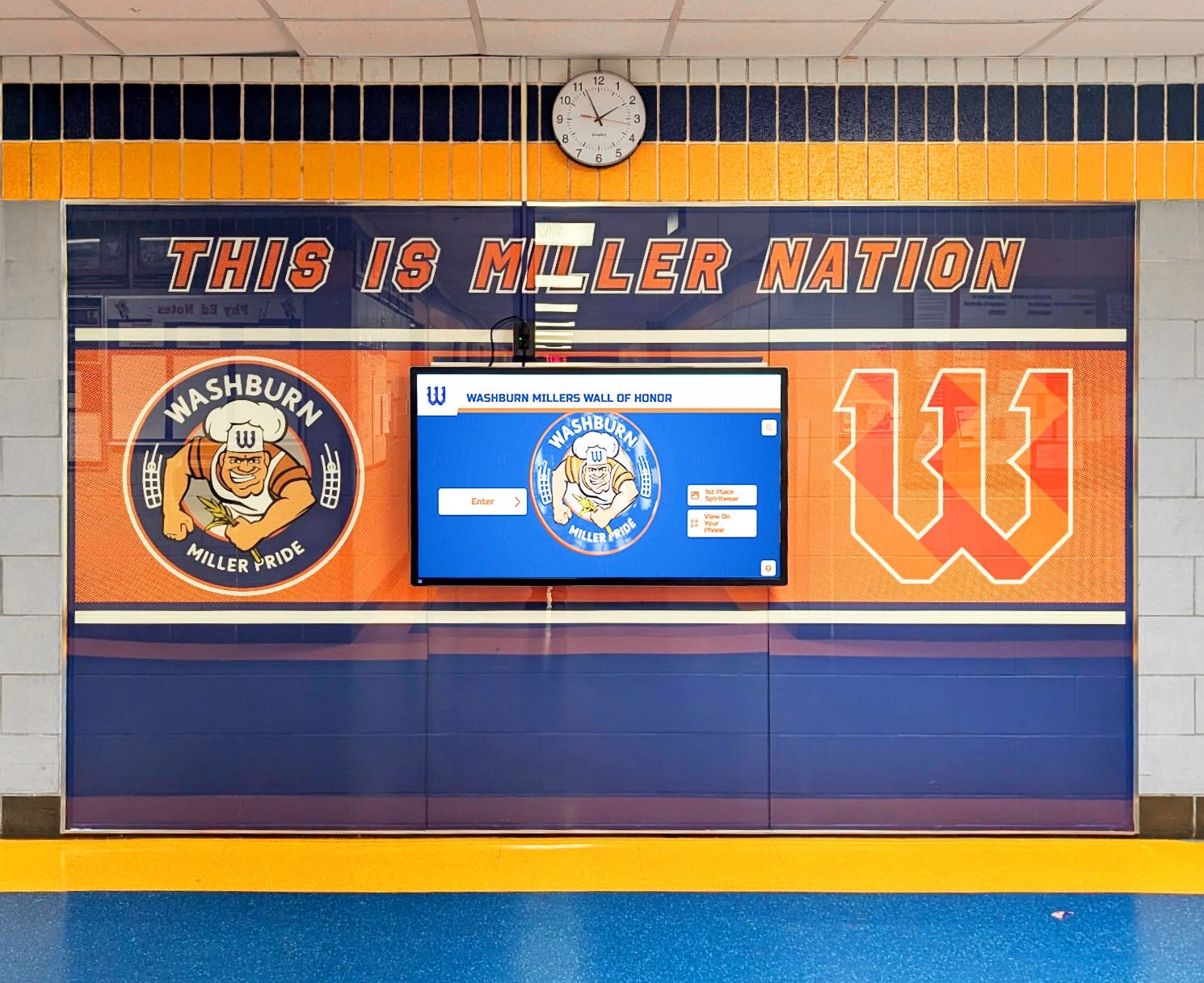
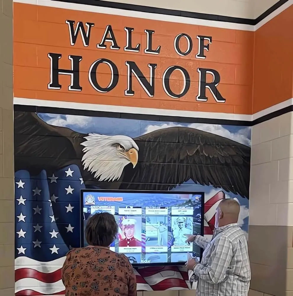
Wall of honor installations depend on network links that stay up through every school event — a completed link flap detection checklist gives IT staff a verified, documented network baseline for each recognition display port
Stable Links Warm Up Recognition Experiences
A recognition display cannot fulfill its purpose if the Ethernet link underneath it cycles up and down during the moments that matter most. Championship content that blanks out during a morning arrival period, a donor recognition panel that fails to load when a benefactor is being shown the lobby, or a hall of fame kiosk that drops its touchscreen session in the middle of a visitor interaction — each of these is a link-flap problem wearing a content problem’s face. The school recognition display link flap detection checklist converts a vague reliability complaint into a specific, verifiable network finding with a concrete fix.
Navigating the digital hall of fame vendor market requires evaluating not just the display platform but the full implementation support model — including whether the implementation team accounts for link-flap detection, STP edge configuration, and carrier-delay settings as part of the initial installation verification, rather than leaving those to school IT staff to discover after the first reported outage.
Rocket Alumni Solutions approaches recognition display installations with a complete network readiness framework: verifying switch port stability, STP configuration, PoE power budget, and cable integrity before the display goes live — so athletic directors, alumni coordinators, and facilities teams have confidence that the recognition experience will be as reliable on event day as it was during the setup walkthrough.
Ready to see a recognition display backed by a complete installation and network verification process?
Schedule a demo with Rocket Alumni Solutions and learn how lobby kiosks, gym hall of fame walls, and corridor recognition screens are deployed with link stability verification, STP configuration, and ongoing network support built into the implementation — not left to troubleshoot after go-live.